Topshine USB 4by4 Console Bedienungsanleitung

Universal Serial Bus
Console
OWNER’S MANUAL
<<Place picture here>>

1
TABLE OF CONTENTS
1. CHECKLIST ----------------------------------------------------------------- P. 2
2. REQUIREMENTS ---------------------------------------------------------- P. 2
3. USB OVERVIEW ----------------------------------------------------------- P. 2
4. MODELS --------------------------------------------------------------------- P. 2
5. INTRODUCTION ----------------------------------------------------------- P. 3
6. FEATURES ------------------------------------------------------------------ P. 3
7. SOFTWARE INSTALLATION ------------------------------------------- P. 4
8. HARDWARE SPECIFICATIONS ---------------------------------------- P. 5
9. HARDWARE DESCRIPTION -------------------------------------------- P. 6
10. POWER ADAPTER -------------------------------------------------------- P. 6
11. CHANGING CONNECTIONS MANUALLY ------------------------- P. 7
12. SOFTWARE FUNCTIONS ----------------------------------------------- P. 10
13. LEGENDS ------------------------------------------------------------------- P. 11
13. APPLICATION PROGRAM --------------------------------------------- P. 11
14. PRINTER DETECTION -------------------------------------------------- P. 15
15. CASCADING USB CONSOLES ---------------------------------------- P. 16
16. NAMING THE PC'S ------------------------------------------------------ P. 17
17. EXTENDING THE DISTANCE ---------------------------------------- P. 18
18. APPLE’S iMAC ------------------------------------------------------------ P. 18
19. RADIO & TV INTERFERENCE ---------------------------------------- P. 18

2
CHECKLIST
Your package should contain the following:
·One USB Console
·One CD Containing the Application Program
·One Power Adapter
·One USB A-to-B Cable
·This User’s Manual
REQUIREMENTS
·Any version Windows 98 or Windows 2000
·Your PC must have a USB port
·You will need a separate USB A-to-B Cable for each system.
USB OVERVIEW
The Universal Serial Bus (USB) is a connection technology that simplifies
communication between computers and their peripheral devices (mice,
keyboards, joysticks, printers, audio components, etc.). The computer is the
USB Host; it connects to the USB Devices via standard USB cables. A USB
Hub acts as a bridge between the USB Host and multiple USB peripherals. Bus-
powered hubs draw electrical current for their operation directly from the USB.
High-powered devices will not work with bus-powered hubs. A high-powered
device is one that can draw up to 500mA from the upstream connection. The
USB Console contains four self-powered hubs (one for each system). Therefore,
any USB device, high or low powered, can be attached to the USB Console.
MODELS
USB 4by4 Console:
Allows up to four USB devices to be accessed by up to four PC’s.
USB 2by2 Console:
Allows up to two USB devices to be accessed by up to two PC’s.

3
INTRODUCTION
Multiple PC’s can share USB peripherals, such as USB printers, USB scanners,
USB cameras, USB keyboards, etc. in various combinations. Access to each
USB device is selected by either manual push buttons on the USB Console or
via a Windows Application Program that displays the status and type of each
USB device attached. Any individual PC can control all connections.
Any PC can connect to any, or all devices, provided that another PC is not
currently using the device. Each PC sees the USB Console as a regular USB
hub to the PC, assuring USB compatibility and meeting all USB specifications.
{4by4 Model}
FEATURES
·Four PC’s share four USB devices (4X4)
·Self-Powered Type Hub
·Each PC sees an independent, four-port USB hub
·Graphical application program and manual device connections
·Fully compliant with the USB Specification 1.1
·Over current detection and prevention
·LED indicators for active ports
·Automatic printer detection and re-connection

4
SOFTWARE INSTALLATION
1. Place CD into the CD-ROM drive.
2. If the installation does not begin automatically, then run SETUP.EXE from
the CD.
3. Follow the installation procedures.
4. Plug in the Power Adapter and insert its plug into the Power Jack on the
USB Console.
5. Connect the USB-A plug from the USB device to any USB Console
downstream port.
6. Connect the USB-B plug from the USB Cable to any USB Console upstream
port.
7. Connect the USB-A plug from the USB Cable to any PC.
8. Each PC sees two USB functions in the USB Console: a hub and a device.
Both are installed.
9. To install the Drivers for the USB Console you may need to insert your
Windows CD.
10. If the Window’s installation box appears select ‘Next’ until you get to this
window.
11. If the box above appears select ‘Browse’ and select the directory that the
USB Console was loaded into during installation (default = C:\Program
Files\USB USB Console), then select ‘Next’ and complete the installation.
5
HARDWARE SPECIFICATIONS
FUNCTION DESCRIPTION
Power Self Powered
Upstream Connectors 4 Type B Receptacles (4by4 model)
2 Type B Receptacles (2by2 model)
Downstream Connector 4 Type A Receptacles (4by4 model)
2 Type A Receptacles (2by2 model)
Port Selection Software or Push-button
Housing Plastic
External Power Supply 5V/2.5A +/-5%
Operating Temperature 5OC ~ 40OC
Storage Temperature -20OC ~ 60OC
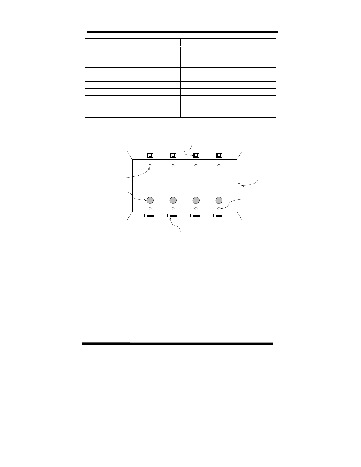
Upstream Port Connectors to PC's
Downstream Port Connectors to Devices
Power Jack
Device LED Indicators
Port Select Push Buttons
PC LED Indicators
USB CONSOLE

6
HARDWARE DESCRIPTION
FUNCTION NUMBER DESCRIPTION
Upstream
Ports
4 (4by4)
2 (2by2)
(USB B-Type Connector)
Use USB Cable with A-B plug to connect to
the PCs.
Downstream
Ports
4 (4by4)
2 (2by2)
(USB A-Type Connector)
Connect to USB devices.
Power Jack 1 Connect to Power adapter.
Device LED
Indicators
4 (4by4)
2 (2by2)
The LED’s near the downstream port
connectors indicate if a device is attached to
that port. It also blinks when that device is
busy. Devices like mice, keyboards, and hubs
are always "busy" even when they are not in
use since they constantly communicate with the
PC.
Port Select
Push Buttons
4 (4by4)
2 (2by2)
These buttons are used to manually switch PC
control of the corresponding USB device. Press
once to determine which PC has control
(indicated by the Controlling PC LED) then
again, while the LED is still on, to select which
PC is to be given control. When the LED turns
off the change will occur.
This is a manual override. The switch will
occur even if a device is busy.
PC LED
Indicators
4 (4by4)
2 (2by2)
I The LED indicators near the PC connectors
indicate which PC is connected to a device in
question. When the pushbutton near the
device’s connector is pressed, the PC LED
indicators above will show which PC is
connected to the device in question. To move
the connection to the next PC, press the button
again, each time connecting to the next PC.
POWER ADAPTER
The USB Console is a self-powered device and will not function without the
Power Adapter attached.

7
CHANGING CONNECTIONS MANUALLY
The Device LED Indicators by each port will be lit when the device attached to
that port is active. These LED’s will also blink when the device is
communicating to the PC.
To determine which PC is connected to a particular device press the button near
the device port. The PC LED Indicator of the PC that is connected to that device
will light.
To change which PC is connected to a device, press the button two consecutive
times within 1 second, of each other. The LED of the next available PC will
light. When the LED turns off, that PC will be connected to the device. If you
want a different PC to be connected to the device, repeat the same procedure
until the LED associated with the PC you desire is lit. Alternatively, you can
quickly press several times before the LED turns off to reach the desired PC.
When no buttons are hit within 1 second the USB Console time outs, and the PC
you selected is now connected to the device.
USB CONSOLE
ADCB
DEVICE 1 DEVICE 4DEVICE 3DEVICE 2
PORT 1 PORT 4PORT 3PORT 2

8
EXAMPLE: CONNECT THE DEVICE ON PORT 2 TO PC ‘C’.
Press the button next to Port 2 (the desired device.)
The LED for PC ‘A’ lights up indicating that PC ‘A’ is connected to Port 2.
Press the button again within 1 second.
USB CONSOLE
ADCB
LED IS LIT
PRESS BUTTON
DEVICE 1 DEVICE 4DEVICE 3DEVICE 2
PORT 1 PORT 4PORT 3PORT 2
USB CONSOLE
ADCB
PORT 1 PORT 4PORT 3
PORT 2
LED IS LIT
PRESS BUTTON
AGAIN

9
The LED for PC ‘A’ will turn off and the LED for the next available PC (in this
case PC ‘B’) will turn on.
If left like this, the USB Console will time out and the device on Port 2 will
be connected to PC ‘B’.
Press the
button again
within
another
second.
The LED
for PC ‘B’
will turn off
and the LED for the next available PC (in this case PC ‘C’) will turn on.
Now let the USB Console time out and the device on Port 2 will be connected to
PC ‘C’.
USB CONSOLE
ADCB
LED IS LIT
PRESS BUTTON
AGAIN
DEVICE 1 DEVICE 4DEVICE 3DEVICE 2
PORT 1 PORT 4PORT 3PORT 2
Dieses Handbuch passt für folgende Modelle
1
Inhaltsverzeichnis


