
Toyotomi FF-55 Bedienungsanleitung

CONTENTS
Page No
SECTION A:
Specifications ··························································· 1
Safety Features ························································· 2
SECTION B:
Safety Tips for Operation ·········································· 3
SECTION C:
Fuel Guide ································································· 4
SECTION D:
Operating Controls and Part Names ························· 5
SECTION E:
Operation
Before Ignition ························································ 7
Operation ································································ 8
Turning Heater Off ·············································· 14
Page No
SECTION F:
Routine Maintenance ·············································· 15
SECTION G:
Troubleshooting ······················································ 17
Section H:
Long Term Storage ················································· 18
Section I:
Installation
Standard Installation Parts ··································· 19
Installation Advice ················································ 20
Installation of Heater and Flue Pipe ····················· 21
Extension Wire of Room Temperature Sensor ····· 22
MODEL FF 55(Type B)
IMPORTANT
1) READ AND UNDERSTAND INSTRUCTIONS BEFORE INSTALLING OR USING HEATER.
2) RETAIN INSTRUCTIONS IN A SAFE PLACE FOR FUTURE REFERENCE.
3) CHECK LOCAL AUTHORITY & BUILDING CODES FOR INSTALLATION REQUIREMENTS.
VENTED HEATING SYSTEM
OPERATION INSTRUCTIONS

Model: FF 55
Heater Efficiency: 92.4% (1)
Heat Rating: High - 5.50 kW (18,800 BTU/h)
Med - 3.74 kW (12,800 BTU/h)
Low - 1.88 kW ( 6,430 BTU/h)
Fuel Consumption: High - 0.622 L/h
Med - 0.423 L/h
Low - 0.213 L/h
Fuel System: External tank (2)
Fuel Type: Paraffin only
Dimensions (W ×H ×D): 496 ×600 ×339 mm
Weight: 17 kg
Vent Pipe Hole: 70 ~ 80 mm diameter
Maximum Length of Vent Pipe System: 3 m, 3 bents or less
Electrical Rating: 230 Volts AC, 50 Hz
Preheat - 260W
Burning - 48W
(1) Heat and vaporized water are produced by fuel combustion. Heat rating does not account for heat loss due to
condensation of water vapor.
(2) External tank to be purchased separately. (Consult your supplier for options.)
SECTION A:
SPECIFICATIONS
1
Flame Sensor
Heater will automatically stop all operations if ignition fails or if flame fails during combustion, in order to
prevent fuel overflow. Error code will be displayed on the digital indicator.
Fuel Strainer
Special strainer catches any dirt or impurities present in the fuel before it is sent to the burner.
Overheat Protector
Automatically stops all operations if heater cabinet reaches abnormally high temperature due to motor
malfunction or abnormal combustion, in order to prevent fire.
Power Failure Recovery System
If power fails during heater operation, heater will turn off. When power resumes, heater will
automatically reignite and maintain the normal selected temperature.
NOTE: The operation varies depending on the time length of power failure and other conditions.
Please see page.14 for more details.
Fully Vented System
Flue pipe system provides outside air for combustion and vents all combustion products to the
outdoors.
1.
2.
3.
4.
5.
SAFETY FEATURES
Your heater is equipped with a number of integral safety features. Please familiarize yourself with these features. If
the heater shuts down due to the operation of any safety device, ensure the problem is identified and corrected.
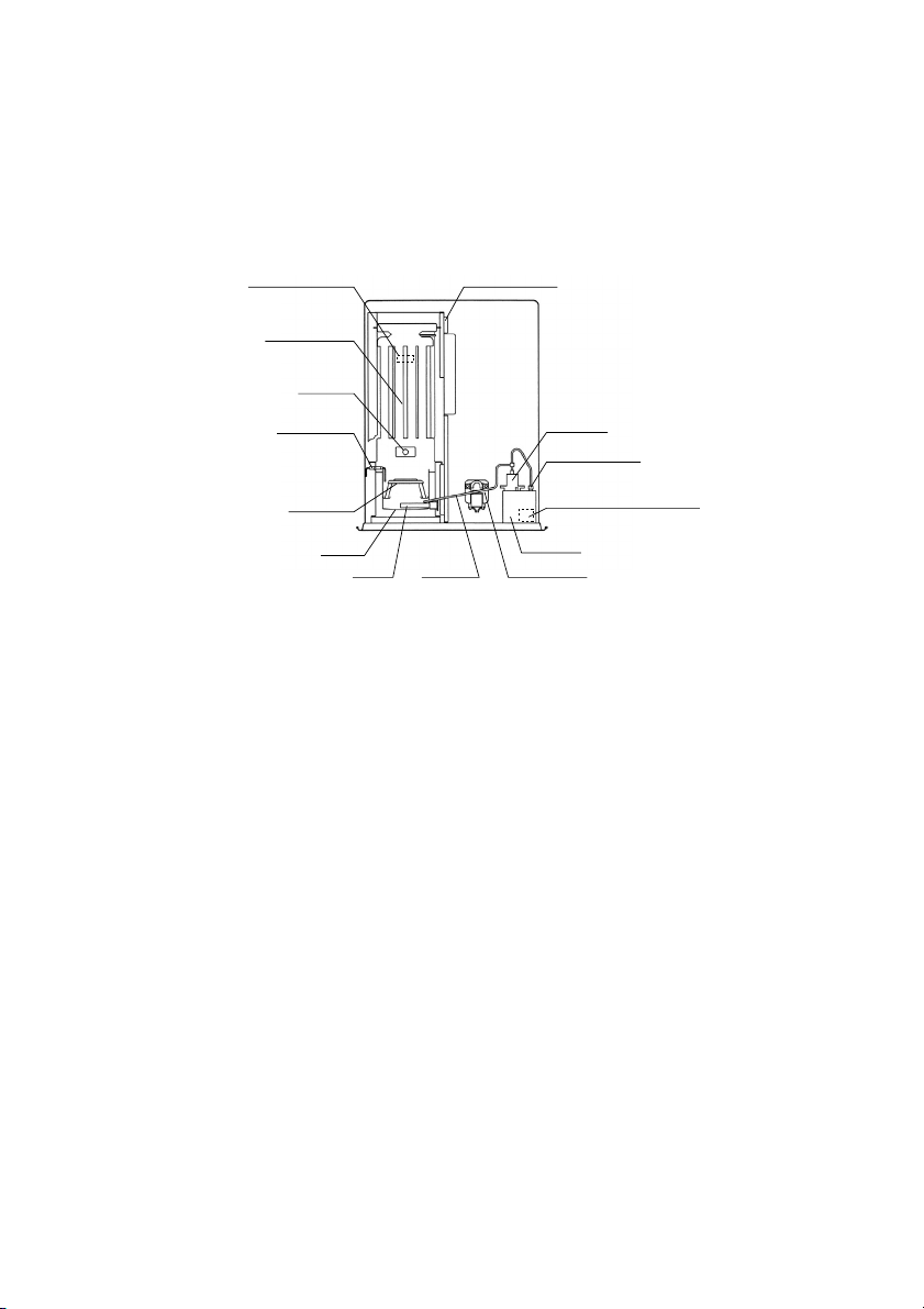
Note that normal combustion flames inside the combustion chamber, can be seen through a “peep hole”, located in
the front bottom left hand corner of the hot air outlet louver’s.
Fuel pipe
Burner ring
Blower motor
Fuel sump
Heat exchanger
Burner
Peep hole
Flame sensor
Igniter
Red reset button
Integral fuel strainer (inside)
Fuel pump
Overheat protector Heat shield plate
2

CAUTION: Heater and vent pipe system must be properly installed before operation. Please follow
instructions under “Installation”, Section I.
• The appliance is not to be used by persons (including children) with
reduced physical, sensory or mental capabilities, or lack of experience
and knowledge, unless they have been give supervision or instruction.
• Children being supervised not to play with the appliance.
• This appliance can be used by children aged from 8 years and above
and persons with reduced physical, sensory or mental capabilities or
lack of experiance and knowledge if they have been given supervision
or instruction concerning use of the appliance in a safe way and un-
derstand the hazards involved.
• Children shall not play with the appliance.
• Cleaning and user maintenance shall not be made by children without
supervision.
1. NEVER use any fuel other than Paraffin. NEVER USE GASOLINE. Use of gasoline can lead to uncontrollable
flames, resulting in destructive fire.
2. Due to high surface temperatures, keep heater away from children, furniture and clothing while in operation. (See
Page 25.)
3. To prevent abnormal operation and prolong heater life, be sure to perform routine maintenance. (See Page 15.)
4. NEVER store or transport fuel in other than a metal or plastic container that is acceptable for fuel and clearly
marked “PARAFFIN”. NEVER store fuel in the living space.
5. Operating Temperature Range
Use heater within the range of temperatures
indicated in the right figure.
Point A: If outside temperature -29˚C
than room temperature has to be -18˚C or above
Point B: If outside temperature -43˚C
than room temperature has to be 16˚C or above -18 -7 4 16
-29 A
B
Room Temperature (˚C)
Outside Temperature (˚C)
-32
-34
-37
-40
-43
Operating Range
RIGHT WRONG
GAS
PARAFFIN
PARAFFIN
Danger
SECTION B:
SAFETY TIPS FOR OPERATION
3
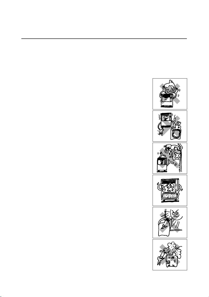
The FF 55 is designed for use with Paraffin. Use of low-quality fuel will cause burner performance to drop, leading
to abnormal combustion and reduced heater life.
Purchase only Paraffin, in non-red cans reserved exclusively for fuel and marked accordingly with the word
“PARAFFIN”. Always store your fuel in a separate area from where you store gasoline for your power equipment to
avoid accidental use of gasoline in your heater.
What to Buy . . .
ALWAYS: Clean and high-quality Paraffin.
ALWAYS: Fuel free of contaminants, water or cloudiness.
NEVER: Gasoline, alcohol, white gas, camp stove fuel or additives.
NEVER: Yellow or sour-smelling fuel.
How to Store It . . .
ALWAYS: Store in a clean container, clearly marked PARAFFIN.
ALWAYS:
Store away from direct sunlight, heat sources or extreme temperature
changes.
NEVER: In a glass container, or one that has been used for other fuels.
NEVER: For longer than six months. Begin each heating season with
fresh fuel; discard at the end of season.
NEVER: In the living space.
Why It is Important . . .
Pure, clean fuel is essential for safe and efficient heater operation. Poor quality or
contaminated fuel can cause:
●Excess tar deposits on burner and flue pipe
●Incomplete combustion
●Reduced heater life
Use of a highly volatile flammable fuel such as gasoline can produce uncontrolla-
ble flames, creating a severe fire hazard.
SECTION C:
FUEL GUIDE
4

5. POWER SAVER/DAY SELECT button
3. TIMER button 9. AUTO indicator
10. TIMER indicator 11. POWER SAVER indicator
12. CHILD LOCK indicator
4. TEMP/TIMER/CLOCK/DAY set
15. SUN MON TUE WED
THU FRI SAT indicator
7. ˚F/˚C toggle switch
6. CHILD LOCK/CLEAR button 2. AUTO button
1. ON/OFF switch
8. ON lamp
13. BURNING MODE indicator
14. ˚F/˚C indicator
Before using heater, familiarize yourself with the following operating controls and part names.
Outlet opening
Inlet opening
Ciraulation air filter 16. Circulation fan
Pipe stopper
18. Power supply cord Fuel inlet
Control panel
Front panel
Combustion
flames peep
hole
Red reset button
Integral fuel strainer
(inside)
Drip tray
Louver
17. Room temperature sensor
SECTION D:
OPERATING CONTROLS AND PART NAMES
5

1. ON/OFF switch:
2. AUTO button:
3. TIMER button:
4. TEMP/TIMER/CLOCK/DAY set:
5. POWER SAVER/DAY SELECT button:
6. CHILD LOCK/CLEAR button:
7. ˚F/˚C switch:
8. ON lamp:
9. AUTO indicator:
10. TIMER indicator:
11. POWER SAVER indicator:
12. CHILD LOCK indicator:
13. BURNING MODE indicator:
14. ˚F/˚C indicator:
15. SUN MON TUE WED THU FRI SAT indicator:
16. Circulation fan:
17. Room temperature sensor:
18. Power supply cord:
Main switch turns heater on and off. When switched
on, heater begins operation and combustion starts
after preheat period.
The button turns weekly timer operation modes on and
off which have been programmed into weekly timer.
The button turns weekly timer set mode on and off.
TEMP/TIMER/CLOCK/DAY set modes can be set by
pressing the ▲/MIN. or ▼/HOUR buttons.
The button turns POWER SAVER operation mode on
and off. When setting weekly timer, the button is used
to select a day of the week.
The button turns CHILD LOCK operation mode on
and off. When setting weekly timer, the CLEAR button
is used.
˚F/˚C toggle switch.
Lit – Heater is in operation.
Flashing – Pre-heating and pre-purging.
Lit – Weekly timer operation is in use.
Lit – Heater operating in weekly timer set mode.
Lit – Heater operation in POWER SAVER mode.
Lit – Heater operation in CHILD LOCK mode.
Lit – Heater operation at high, medium or low
combustion.
Lit – Digital indicator shows current temp.
Flashing – Current temp can be changed.
Lit – Digital indicator shows current day or timer day.
Three speed motor supplies high-capacity warm air
flow during high combustion for heating room up
quickly, and low or medium-capacity warm air flow
during low or medium combustion for maintaining
comfortable room temperature.
Constantly senses room temperature and supplies
information to heater so that desired room
temperature can be maintained.
The position of room temperature sensor can be
changed by using the extension wire (*optional) (See
Page 26.)
For use in 230V AC, 50Hz electrical outlet.
6

Red Reset Button
BEFORE IGNITION
1. Open the Valve(s)
Open the valve(s) of the external fuel tank.
2. Start the Fuel flow
If using heater for the first time, press the red reset button in order to send fuel to
the fuel sump and release.
NOTE: Make sure there is no fuel leakage from the fuel line or joints.
Also make sure fuel tank is not too high. See installation instructions.
3. Connect the Heater
Connect heater into a 230V AC, 50Hz electrical outlet. On digital indicator pre-set
“Two Dashes” will be showing.
NOTE: Do not connect to an outlet shared with other appliances.
4. Set Clock
IMPORTANT: Clock on the heater must always be set to current time and day.
NOTE: The “▲MIN.” or “▼HOUR” button will change the time every one (1) unit. Holding the button continuously
will cause the time to change rapidly.
NOTE: In the event of a power failure (more than approx. 30 min.), all clock and day may be cancelled.
5. Setting of the Time and a Day of the Week.
1) Current time is not set yet. (All signs light.)
Press the “▲MIN.” button or “▼HOUR” button while in not operation. (Power switch is off.)
0:00 (midnight) is indicated on the display. (All signs except the colon are blinking.)
2) Setting of the current time
Press the “▲MIN.” button to set minutes and press the “▼HOUR” button to set hours.
When pressing the “▼HOUR” button, the sign will change as follows.
“0:00” ➞“1:00” ➞··· ➞“11:00” ➞“12:00” ➞“13:00” ➞··· “23:00” ➞“0:00” ➞···
When pressing the “▲MIN.” button, the sign will change as follows.
“0:00” ➞“0:01” ➞··· ➞“0:59” ➞“0:00” ➞···
Press the “SET” button to complete the set of the current time.
SECTION E:
OPERATION
7

3) Setting of a day of the week
“dAy” sign is shown on the display and all of a day of the week blink.
Press the “▲MIN.” button or the “▼HOUR” button to set a day of the week. A day of the week will blink. (Initial
setting is “SUN”.) The other days of the week will go off. Select a day of the week by using the “▲MIN.” or the
“▼HOUR” button. When pressing the “▲MIN.” button, the sign will change as follows.
“SUN” ➞“MON” ➞“TUE” ➞“WED” ➞“THU” ➞“FRI” ➞“SAT”
When pressing the “▲MIN.” button at the position of “SAT”, you can hear the beep sound and “SAT” is not
changed any more. When pressing the “▼HOUR” button, the sign will change as follows.
“SAT” ➞“FRI” ➞“THU” ➞“WED” ➞“TUE” ➞“MON” ➞“SUN”
When pressing the “▼HOUR” button at the position of “SUN”, you can hear the beep sound and “SUN” is not
changed any more.
Press the “SET” button to complete the set of a day of the week. The current time and a day of the week will
show on the display.
NOTE: If the ON/OFF switch is pressed during resetting of the current time and a day of the week after setting
the time and a day of the week, the set mode of the current time will terminate and the operation will start.
If a day of the week is set, the time is fixed at the resetting time. If a day of the week is not set, the
contents of the setting are deleted.
OPERATION
MANUAL OPERATION
Operation of the heater is under the direct control of the user. Heat output will, however, be automatically
adjusted in accordance with the room temperature registered by the temperature sensor.
1. Turning Heater ON
A. Press ON/OFF switch to “ON” position. The current room temperature and the set temperature will be
shown on the digital indicator. ON lamp will start to flash and then blower motor and ignition will start. This
lamp will continue to flash during the preheating time.
B. After approx. 1.5 – 4 minutes ignition will take place. (*) After ignition, ON lamp will change flashing to
continuous. Circulation fan will turn on after approx. 2 minutes.
NOTE: (*) Pre -heating depends on the room temperature.
Room temperature:
under 0˚C 4 minutes
0˚C - 15˚C 2 minutes
15˚C 1.5 minutes
8

2. Adjusting Room Temperature
A. Press the “▲MIN.” or “▼HOUR” button. ˚F or ˚C will start to flash.
NOTE: The“▲MIN.” or “▼HOUR” button will change the temperature in increment of 1˚C (2˚F).
B. Press the “▲MIN.” or “▼HOUR” button as required. Room temperature can be set from 10˚C (50˚F) to 32°C
(90˚F). (Initial setting : 13˚C (56˚F))
NOTE: Desired temperature setting will be displayed on the digital indicator when you set the room
temperature.
C. When room temperature reaches the selected setting, heater will automatically shift to “MED” or “LOW”
burning mode to maintain the desired temperature.
When room temperature exceeds the selected setting by approx. 2˚C (4˚F), the heater will automatically shut
off. As room temperature drops, the heater will automatically re-start to maintain the desired temperature.
POWER SAVER OPERATION
The Power Saver mode reduces the frequency of ignition actions, to save electric consumption.
Press the POWER SAVER (DAY SELECT) button “ON” while in operation to start the operation of the “POWER
SAVER”. “POWER SAVER” sign will be shown on the digital indicator.
When the room temperature exceeds the selected setting by approximately 6˚C (10˚F), the heater will
automatically shut off. As the room temperature becomes lower than the selected setting, the heater will
automatically re-start to maintain the desired temperature.
Approx. +6˚C
Approx. +1˚C
SET
TEMP.
High Medium Low Off Re-lgnition
Approx. +2˚C
Approx. +1˚C
SET
TEMP.
High Medium Low Off Re-lgnition
9
Inhaltsverzeichnis
Andere Toyotomi Heizsystem Handbücher

Toyotomi
Toyotomi FF-V30T Bedienungsanleitung

Toyotomi
Toyotomi FF-55T Bedienungsanleitung

Toyotomi
Toyotomi FQ-C70 Bedienungsanleitung

Toyotomi
Toyotomi Oil Miser OM-22 Bedienungsanleitung

Toyotomi
Toyotomi FF-V30 Bedienungsanleitung

Toyotomi
Toyotomi Oil Miser 23 Bedienungsanleitung

Toyotomi
Toyotomi FF-V30T Bedienungsanleitung

Toyotomi
Toyotomi FF-55T Bedienungsanleitung

Toyotomi
Toyotomi FR-700F Bedienungsanleitung

Toyotomi
Toyotomi Laser 60AT Montageanleitung


