Uchida Yoko TAPIT-50W Bedienungsanleitung

June 28,2006
OHKURA KOGYO CO.,LTD.
UCHIDA TAPIT-50W
SERVICE MANUAL
UCHIDA YOKO CO., LTD.

1
Safety Instructions
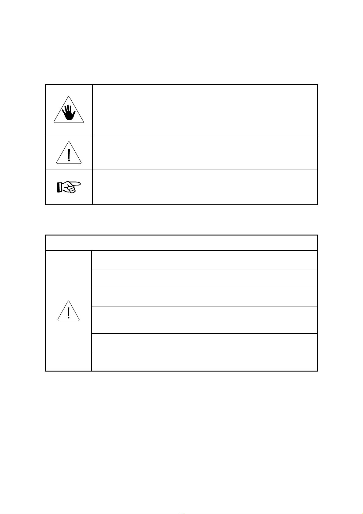
Definition of Symbols and Notes
In this manual following names and signs stand for possible dangers.
Danger
This Symbol stands for immediate danger threatening the life and health of
persons.
Disregarding these instructions may cause severe damage to health and even
serious injuries.
Caution
This symbol stands for an endangering situation that may occur.
Disregarding these instructions may lead to slight injuries or damage to property.
Note
This symbol stands for notes, operational hints and other useful information.
They are convenient for exploiting the machine’s functional abilities.
Caution
1. The internal temperature of the machine is very high during operation. Do not
touch the inside of the machine. Touching it may cause a burn.
2. When the power is turned on, do not put a hand inside the machine and in the
tape passage groove. There is a danger of an injury.
3. Do not spill any liquid such as water over the machine. Do not use any wet
article. Using such an article may cause an electric shock or failure.
4. When a failure occurs, lightning may occur or the machine is not used, pull out
the power plug from the plug socket. Keeping the machine in such a condition
without pulling out the power plug may cause a fire or electric shock.
5. Be sure to ground the machine. Operating the machine without grounding it
may cause an electric shock or fire.
6. Do not install the machine in an unstable place such a shaky base and an
inclined floor. Such installation may cause a fall or turnover, resulting an injury.

2
Contents
1. Brief Description of Each Section .........................................................................................3
1. Reference assembly drawing of each section [Brief functional description of each section] 3
2. Function of each sensor or switch .......................................................................................... 4
3. Inching.................................................................................................................................... 5
2. Adjustment of Main Frame Section...................................................................................... 6
1. Replacement of spindle timing belt........................................................................................ 6
2. Adjustment of main spindle timing belt ................................................................................. 8
3. Adjustment of cutter section ...............................................................................................10
1. Replacement of cutter...........................................................................................................10
4. Adjustment of heater...........................................................................................................15
1. Replacement of heater.......................................................................................................... 15
5. Adjustment of hold plate section.........................................................................................18
1. Position check of sensor mounting plate.............................................................................. 18
2. Adjustment of sensor mounting plate................................................................................... 20
3. Adjustment of tape detecting plate....................................................................................... 23
6. Adjustment of tape reel section...........................................................................................25
1. Replacement of tape brake. .................................................................................................. 25
2. Adjustment of tape break........................................................................................................ 27
7. Adjustment of tape guide section........................................................................................28
1. Adjustment of wire............................................................................................................... 28
8. Adjustment...........................................................................................................................29
1. Installation of foot switch.....................................................................................................29
2. Starter Switch ....................................................................................................................... 29

3
1. Brief Description of Each Section
1. Reference assembly drawing of each section
[Brief functional description of each section]
1: Main frame section
[Internal side plate, main motor, main spindle]
2: Heater/cutter section
[Heater for deposition, tape press-down, tape cutting]
3: Hold plate section
[Tape deposition support plate, tape press-down support plate, tape detection]
4: Tape feed/tightening section
[Take lead-in, tightening]
5: Tape reel section
[Tape reel setting, tape braking]
6: Tape guide section
[Fed-out tape guide, tape holding]
7: Main unit section
[Outside covers, switches]

4
2. Function of each sensor or switch
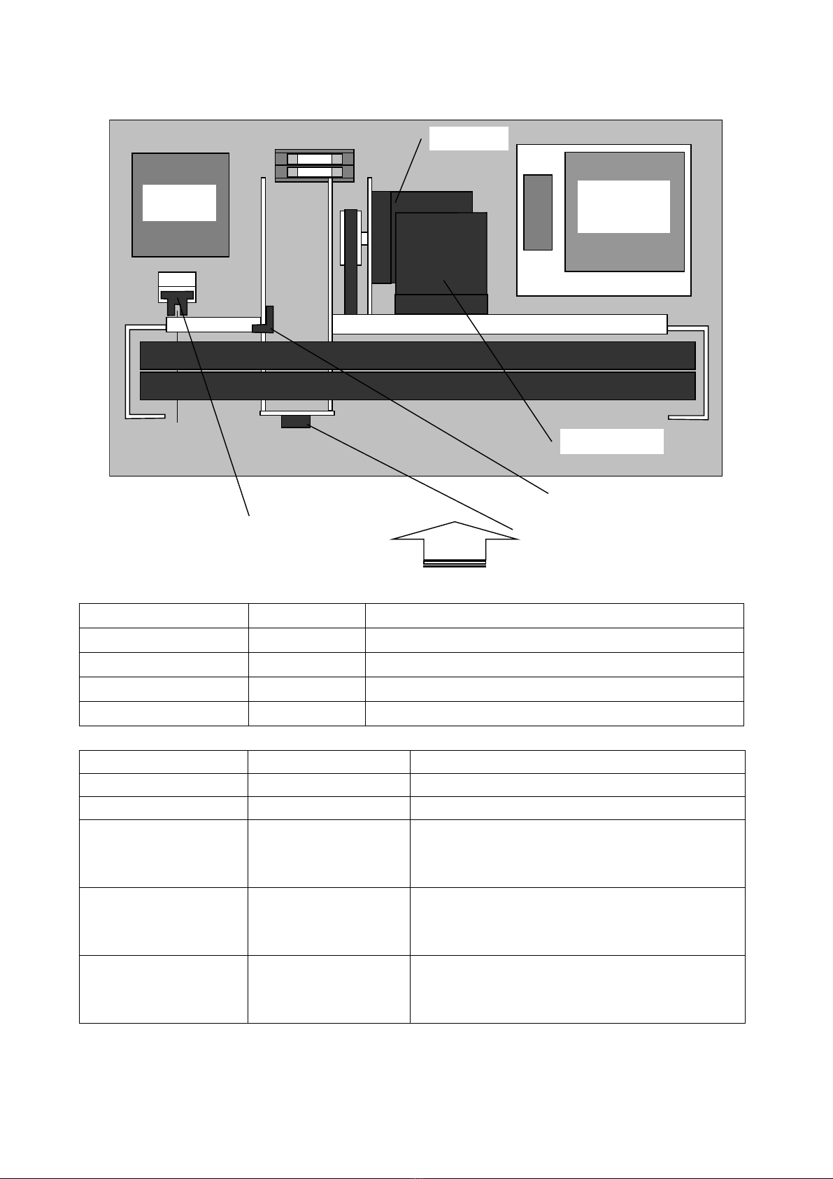
Near side
Item sensor
Taper sensor
Main spindle sensor A/B
Main motor
Tape feed motor
PCB
OUK-071D
Heater
transformer
Sensor name Model No. Function
Main spindle sensor A EE-SX670 Detects the main spindle position.
Main spindle sensor B EE-SX670 Detects the main spindle position.
Tape sensor EE-SX671 Detects whether a tape is at the bundle enable position or not.
Item sensor KR895 Detects whether an item is on the table or not.
Switch name Model No. Function
POWER switch JW-M21RKK Turns on and off the main power supply.
Temperature control knob RV24YN20SB1kΩControls the heater temperature
START switch KSW-R00 (switch)
KTA-0227
(STRAT key top)
Starts bundling
Returns the main spindle to the initial position.
Selects between enable/disable for the item sensor.
AUTO switch KSW-R00 (switch)
KTA-0117
(AUTO key top)
Sets the AUTO start function.
TAPE FEED switch KSW-R00 (switch)
KTA-0117
(TAPE FEED key top)
Feeds the tape.

5
3. Inching
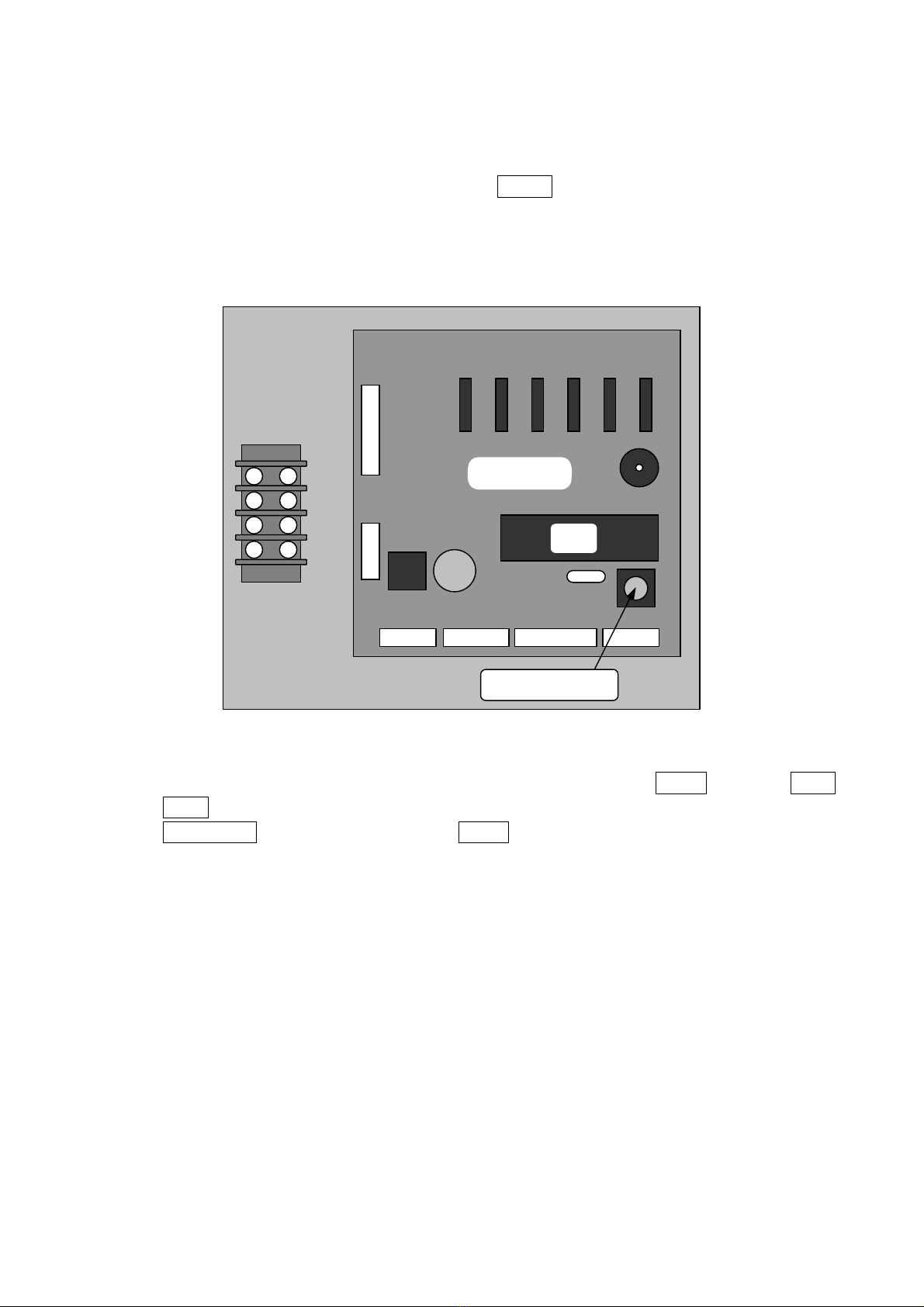
Inching is performed by a switch provided on the PCB. While the INCHING switch is pressed,
the main motor is operated.
After pressing the INCHING switch, press the START switch to return the main spindle to the
initial position. The main motor will be operated and the main spindle will be returned to the
initial position. If the main spindle is at the initial position even after the INCHING switch is
pressed, the main motor is not started.
OUK-071D
INCHING Switch
CPU
In addition, inching can be performed according to the condition of the switches when the
power switch is turned on. If the power switch is turned on while the AUTO switch and TAPE
FEED switch are pressed, the INCHING mode can be set. Under the INCHING mode, if the
TAPE FEED switch is pressed while the AUTO switch is pressed, inching will be performed.
To release the INCHING mode, turn off the power.

6
2. Adjustment of Main Frame Section
1. Replacement of spindle timing belt
1. Remove the rear table, rear cover, front table and switch panel.
M4 x 8
set screw
x 2
2. Loosen the main motor mounting screw.
3. After removing the mounting screw fixing the roller pressure cam, remove the roller pressure
cam.

7
4. Remove the old timing belt and replace it with a new timing belt.
5. Mount the roller pressure cam.
6. Make adjustment according to “2. Adjustment of spindle timing belt.”

8
2. Adjustment of main spindle timing belt
After the main motor or the gear head is replaced, the main spindle timing belt (Hereinafter
referred to as the belt) must be adjusted.
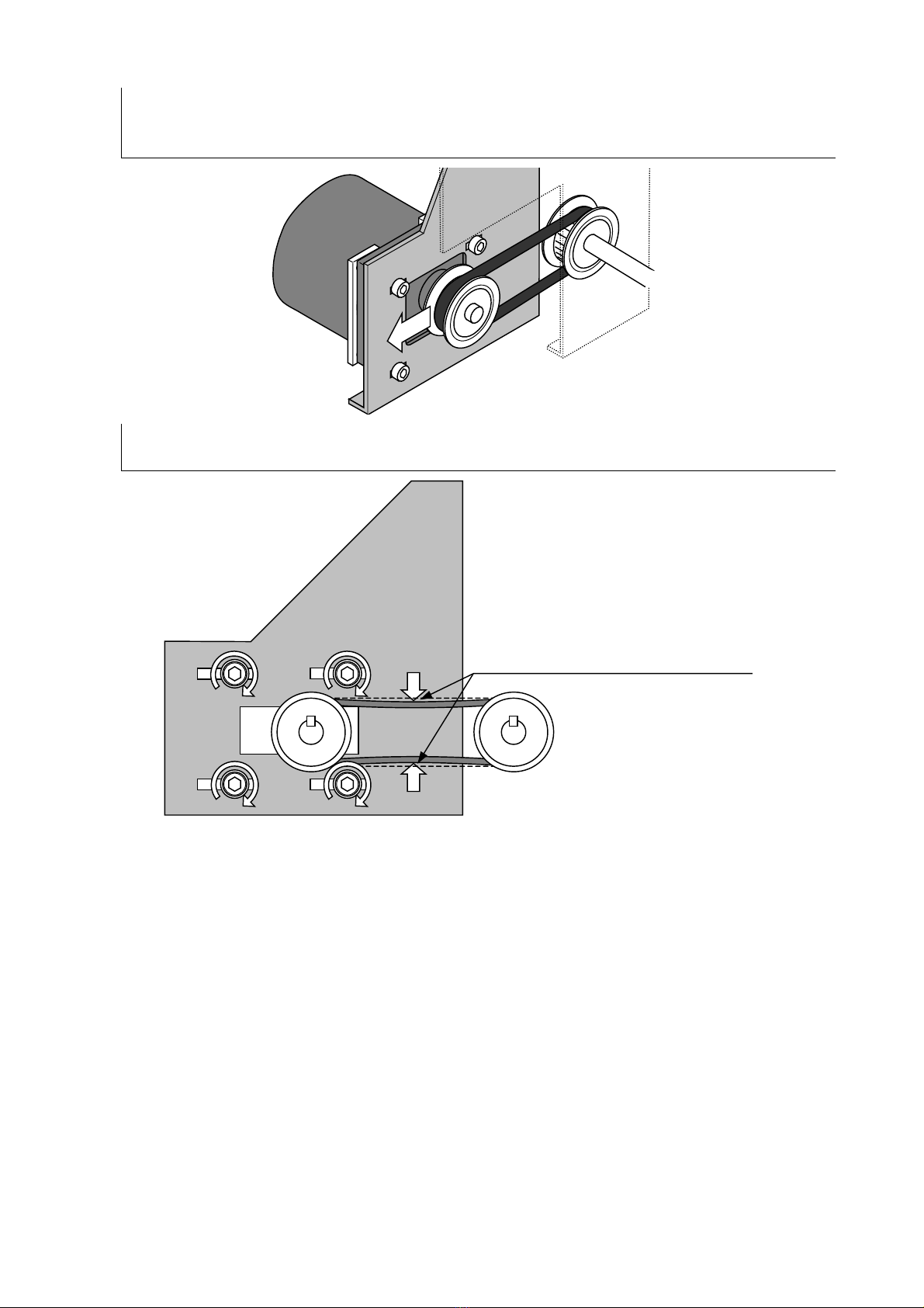
1. Tentatively fit the main motor and the gear head loosely using mounting screws and fix the
motor side pulley on the gear head spindle.
Clearance between the metal
plate and the pulley: 9mm
2. Put the belt on the motor side pulley and main side pulley.

9
3. Pull the main motor backward to uniform the belt tension between on the upper side and on the
lower side, and tighten the mounting screws to an extent that the main motor may not be moved
easily.
4. Push the middle of the belt lightly on the upper side and lower side with fingers and fix the main
motor at the position where the middle of the belt is flexed about 1 to 2 mm.
The belt should flex 1 to 2mm
when lightly pushed down with your fingers.
* The belt will be considerably tightly stretched.
Inhaltsverzeichnis