UfE ENS31 Technische Daten

ENS31 Automatic Isolation Unit
Product Description
Issue 09/2005

Page 2 of 20 Product Description ENS31 Version: A.02
Issue: 20.09.2005
UfE Umweltfreundliche Energieanlagen GmbH
Joachim-Jungius-Straße 9
D–18059 Rostock
Tel.: +49 3 81 / 405 97 05
Fax: +49 3 81 / 405 97 03
E-mail: [email protected]
web: www.ufegmbh.de
Note
If you have any queries and need to contact UfE GmbH, always have the
serial number close to hand in order to make reference to it. We do not
claim the documentation is free of errors and mistakes. Please inform
UfE GmbH of any errors found in the documentation.
© Copyright
This Product Description is the copyright of UfE GmbH.
This manual is intended for the customers and project planner. It contains
instructions and information which must not be copied, distributed or
transferred by technical data methods nor used for the purpose of compe-
tition, either as an entirety or as extracts, without the necessary authorisa-
tion.
Contravention could lead to prosecution and obligation to pay damages.
All rights reserved, particularly in the case of patent application or other
registrations.
We reserve the right to make technical modifications without notice.
Note
The ENS31 isolation unit and the measuring method are protected by
patent.

Table of Contents
Version: A.02 Product Description ENS31 Page 3 of 20
Issue: 20.09.2005
1 Purpose of the Product..........................................................4
2 System Description ................................................................5
2.1 Principles of functioning..................................................5
2.2 LCD displays and LEDs..................................................6
2.3 Connections ...................................................................7
3 Behaviour of the Isolation Unit..............................................8
3.1 General information........................................................8
3.2 Fluctuations in the mains power supply..........................8
3.3 Deviation of the mains power frequency.........................9
3.4 Impedance jumps ...........................................................9
3.5 Influence of isolation units on each other .....................10
3.6 Optimised impedance measurement process ..............10
3.7 Automatic calibration of the impedance measurement.11
3.8 Automatic adaptation of switching thresholds to the
mains power conditions ................................................12
3.9 Automatic synchronisation / limitation of signal strength
in the case of frequent use of the ENS .........................13
4 Installation.............................................................................14
4.1 Mechanical installation .................................................14
4.1.1 Transport and unpacking .............................14
4.1.2 Conditions for installation ............................14
4.1.3 Preparing the electrical/meter cabinet .........15
4.1.4 Mounting on the top hat rail .........................15
4.2 Electrical connections...................................................16
4.2.1 Basic configuration ......................................16
4.2.2 Demands of the switching elements ............16
4.2.3 Circuitry .......................................................17
5 Advantages for the Customer .............................................19
6 Technical Data ......................................................................20

Chapter 1
Purpose of the Product
Page 4 of 20 Product Description ENS31 Version: A.02
Issue: 20.09.2005
1 Purpose of the Product
The automatic, three-phase isolation unit is an automatic switching unit
used to connect decentralised power generators safely to the public elec-
tricity supply.
The ENS31 isolation unit has been conceived as an independent unit for
monitoring 3-phase power feeding systems. It prevents uncontrolled island
effects following failure or shutdown of the public electricity supply.
The ENS31 complies with DIN VDE 0126-1-1 and is approved as a sub-
stitute for manual isolation devices up to a 30 kW feeding power.
By implementing this automatic isolation unit, it is possible to dispense
with a manual isolation unit which must be accessible to the public elec-
tricity supply authorities at all times.
The feeding systems can be:
•photovoltaic systems,
•small hydroelectric power stations,
•block-type thermal power stations,
•fuel cells,
•small wind energy plants.

Chapter 2
System Description
Version: A.02 Product Description ENS31 Page 5 of 20
Issue: 20.09.2005
2 System Description
2.1 Principles of functioning
The ENS31 automatic isolation unit continually monitors
•overvoltage and undervoltage
•frequency deviation
•impedance jumps
in the public electricity supply.
In the event of faults in the mains supply, the ENS31 interrupts the feed-
ing of electricity in the mains to prevent island effects.
The contact-based disconnection is initiated by externally provided con-
tactors with positively driven NC contacts. These contactors are controlled
in two channels by the ENS31 via relays Rel1 and Rel2. Request for the
switching status of the external contactors occurs via two acknowledge-
ment inputs.
After switching on, Contactor 1 is activated first and Contactor 2 is only
enabled after reaching and testing the switching status.
Note
The ENS31 cannot be switched on without the acknowledgement inputs
being correctly wired.
The safety functions are executed in a 3-channel system, whereby each
channel measures the mains voltage, mains frequency, mains impedance
and the voltage of another channel independently.
The channels monitor each other mutually (refer to the error protection in
accordance with DIN VDE 0126) to increase error protection. Therefore,
recurrent tests can be dispensed with.
Note
Further information on the principles of functioning is available on our
Internet site at www.ufegmbh.de.

Chapter 2
System Description
Page 6 of 20 Product Description ENS31 Version: A.02
Issue: 20.09.2005
2.2 LCD display and LEDs
The following indicators are mounted on the front side of the ENS31:
X XXXXX
AB
C
D
A) LCD
The unit and mains power status is shown on a 2-line LC display. Each
line can display 16 characters.
B to D) LEDs
In addition to the LCD, the unit and mains power status are also indicated
by three LEDs (red, green, yellow)
(B = L1, C = L2, D = L3).
Note
The meaning of the indicators is described in the Operating Manual.
Chapter 2
System Description
Version: A.02 Product Description ENS31 Page 7 of 20
Issue: 20.09.2005
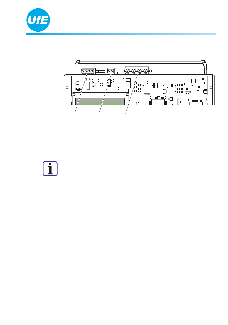
2.3 Connections
The following connections are provided at the top edge of the ENS31:
<RELAIS
1 234
<KONTAKTE
12
<NETZ
NL1L2L3
AB C
A4 connection terminals for contactor control, potential-free,
B2 connection terminals to connect positively driven auxiliary contacts,
C4 connection terminals to connect three phases and the neutral
conductor.
Note
The connection of the unit is described in the Installation Manual.

Chapter 3
Behaviour of the Isolation Unit
Page 8 of 20 Product Description ENS31 Version: A.02
Issue: 20.09.2005
3 Behaviour of the Isolation Unit
3.1 General information
The ENS31 monitors the mains power supply and prevents uncontrolled
island effects developing in the event of a power failure or the mains be-
ing switched off.
It reacts to fluctuations in:
•voltage,
•frequency,
•impedance
of each individual phase.
Note
The default settings can be changed, if necessary. The ENS manufac-
turer must be informed of these requirements, however, prior to con-
figuration.
3.2 Fluctuations in the mains power supply
The threshold values for the mains power supply are set as follows:
Fluctuation Threshold value Test interval
Overvoltage 300 V Every 20 ms
(fast shutdown)
Overvoltage 264 V Every 200 ms
Undervoltage 130 V Every 20 ms
(fast shutdown)
Undervoltage 184 V Every 200 ms
Disconnection from the mains is also triggered when the 10-minute aver-
age value of the mains supply exceeds the setpoint value of 230 V by
more than 10% (testing the mains quality).

Chapter 3
Behaviour of the Isolation Unit
Version: A.02 Product Description ENS31 Page 9 of 20
Issue: 20.09.2005
3.3 Deviation of the mains power frequency
The testing of the frequency of the public electricity supply is completed
by all three channels independent of each other via a protective resistor di-
rectly in the mains power supply.
The threshold values for the mains frequency are set as follows:
Fluctuation Threshold value Test interval
Overfrequency 50.2 Hz Every 200 ms
Underfrequency 47.5 Hz Every 200 ms
Channel 1 also measures the phase position between the outer conductors.
In the event of a phase difference in excess of 30 degrees, the feeding
point is disconnected from the power supply.
If the rate of change of the frequency (RoCoF) exceeds 1 Hz/s, discon-
nection from the supply is also triggered.
3.4 Impedance jumps
All three channels measure the mains impedance. The time-dependent
change of voltage near the crossover (phase shift), caused by test signals,
with various voltage values forms the basis for calculating the mains im-
pedance.
All the impedances measured in one second are used to establish an aver-
age value. The number of measuring pulses is dependent on the number of
ENS connected in the network.
Depending on the power characteristics, the triggering threshold for an
impedance jump is adapted between 1 ohm and 0.2 ohm.
Note
A threshold of 0.5 ohm is set ex works.
The automatic adaptation of the switching threshold is described in Sec-
tion 3.8.

Chapter 3
Behaviour of the Isolation Unit
Page 10 of 20 Product Description ENS31 Version: A.02
Issue: 20.09.2005
3.5 Influence of isolation units on each other
When isolation units of the type ENS31 are used, they can be imple-
mented in dense proximity in the public electricity supply without it lead-
ing to operational problems. Even in the case of long network spurs and a
mains supply subject to frequent faults, unproblematic operation can be
guaranteed.
The ENS31 automatically adapts to these difficult power supply condi-
tions. To achieve this, the following processes are integrated in the
ENS31:
•optimised impedance measurement process,
•automatic calibration of the measured impedance change,
•automatic adaptation of switching thresholds to frequent fluctuations
and interference levels
•automatic synchronisation and limitation of signal strength in the case
of frequent use of the ENS
3.6 Optimised impedance measurement process
The optimised impedance measurement process improves the resolution
and interference resistance of the impedance measurement on a large
scale. Centralised ripple control signals and frequency converters hardly
influence measurements.
An island effect is recognised by a sudden increase in the mains power
impedance.
phase shift
measured by
the ENS
test signal
island formation
local power supply
average vo
l
tage supp
l
y
ENS
Inhaltsverzeichnis


