UHVD MASC Bedienungsanleitung

MASC Revision: 1.1 Author: N.Carapiet
QUICK START GUIDE
Product: MASC Multi Axis Stepper Controller
Product Description
Stepper Motor Controller

MASC QUICK START GUIDE
Page 2of 19
TABLE OF CONTENTS
Table of Contents
IMPORTANT SAFETY INFORMATION!.........................................................................................4
POSITION CONTROL SYSTEMS ARE INHERENTLY HAZARDOUS. EVEN A SMALL MOTOR, IF
COUPLED TO A LEADSCREW, GEARBOX, OR ANY OTHER FORM OF MECHANISM THAT
PROVIDES A MECHANICAL ADVANTAGE, CAN GENERATE CONSIDERABLE FORCE AND
COULD CAUSE SERIOUS INJURY. INCORRECT OPERATION CAN ALSO LEAD TO DAMAGE
TO THE MOTOR OR ASSOCIATED MACHINERY. IT IS ESSENTIAL THAT THE PURPOSE OF
THE VARIOUS FAULT DETECTION FEATURES BUILT INTO THE MASC’S ST5-Q CONTROLLER
BE FULLY UNDERSTOOD AND USED CORRECTLY. .......................................................................4
AS SUCH, INSTALLATION MUST BE CARRIED OUT ONLY BY COMPETENT PERSONS WHO ARE
FAMILIAR WITH ELECTRONIC CONTROL SYSTEMS.......................................................................4
OVERVIEW......................................................................................................................................4
LAYOUT - FRONT...................................................................................................................4
LAYOUT –REAR ....................................................................................................................5
GETTING STARTED.......................................................................................................................5
UNPACKING ...........................................................................................................................5
CONNECTIONS TO MASC.....................................................................................................6
3.2.1 Power Connection.................................................................................................................7
3.2.2 D Type Connectors...............................................................................................................7
3.2.3 M12 Connectors....................................................................................................................8
3.2.4 Single Axis Systems .............................................................................................................8
3.2.5 Multi Axis Systems................................................................................................................9
CONNECTIONS TO DEVICES ...............................................................................................9
3.3.1 M12 Connectors....................................................................................................................9
3.3.2 UTO Connectors.................................................................................................................10
3.3.3 LEMO Connectors ..............................................................................................................11
3.3.4 Encoder Connections..........................................................................................................11
CONNECTION TO PC...........................................................................................................12
CONNECTION TO JOG BOX................................................................................................13
CHECKS................................................................................................................................13
OPERATION..................................................................................................................................14
JOG BOX...............................................................................................................................14
4.1.1 Jog Mode ............................................................................................................................15
4.1.2 SEQUENCE MODE............................................................................................................16
4.1.3 Limits and Datum Mode......................................................................................................18
4.1.4 Status Mode........................................................................................................................19
JOG EMULATOR ..................................................................................................................19


MASC QUICK START GUIDE
Page 4of 19
IMPORTANT SAFETY INFORMATION!
This document is intended as a user guide to operation as determined by the design.
Position control systems are inherently hazardous. Even a small motor, if coupled to a leadscrew,
gearbox, or any other form of mechanism that provides a mechanical advantage, can generate
considerable force and could cause serious injury. Incorrect operation can also lead to damage to
the motor or associated machinery. It is essential that the purpose of the various fault detection
features built into the MASC’s ST5-Q controller be fully understood and used correctly.
As such, Installation must be carried out only by competent persons who are familiar with electronic
control systems
OVERVIEW
The MASC is a single axis stepper motor controller in a compact rack mountable enclosure. It is a
versatile, high-performance microstepping packaged unit suitable for light industrial and scientific uses
where precision and system-level integration are required. Monitoring and control can be achieved over
a RS-485 serial connection that can be easily configured in multi-drop for the coordinated use of several
drivers over the same connection. RS232 is also an option for single axis applications.
The MASC controller consists of a ST5-Q programmable microstepping drive and an integrated 24V
DC universal input power supply built into a 21HP 3U subrack unit for mounting into industry standard
19” racks. This allows for up to four MASC units to be fitted in one standard 84HP wide rack.The MASC
is supplied for plug and play operation with UHV Design stepper motorised products. The MASC will be
factory preset when purchased with a stepper motorised device.
LAYOUT - FRONT
On/Off Switch
Axis Identification
Sticker (if more than
one axis configured).
Status LED’s

MASC QUICK START GUIDE
Page 5of 19
LAYOUT –REAR
GETTING STARTED
UNPACKING
Included in each package:
MASC (stepper motor controller) x 1
MASC-TP (RS485/232 terminator plug) x 1
MASC-JC-03 (PC/Jog Box connection lean) x 1
Mains Power
Input
Mains Fuse
RS-485/RS232
in (from PC or
Jog Box)
RS-485/RS232
out (terminator
or next MASC)
Stepper
Motor Socket
Limit & Home
Switch Socket
Encoder
Socket
Brake Socket

MASC QUICK START GUIDE
Page 6of 19
MASC-USB (USB to serial RS-485 converter) x 1
UK Mains power Lead x 1
US Mains power lead x 1
EU Mains power lead x 1
Additional cables and jog box for connection to UHV Design stepper motorised products are
provided with the control packages and should be configured when purchasing the device. Cables
may be packaged within the MASC packaging.
CONNECTIONS TO MASC
A dedicated series of cables that allow connection between the MASC and any UHV Design stepper
motorised devices are available and should be configured when purchaing the MASC and device
together.
Note: It is important not to switch on the MASC until all connections are securely made. Unplugging
cables, in particular the motor cables, whilst the MASC is switched on can cause damage to the
MASC or motor.

MASC QUICK START GUIDE
Page 7of 19
Note: all connectors going into the back of the MASC are straight. Connectors going to motors
and switches are generally right angled.
3.2.1 Power Connection
1. Choose appropriate power lead for region e.g. UK, US
2. Push plug into IEC socket on rear of MASC.
3.2.2 D Type Connectors
1. Push connector into socket
2. Rotate locking screws clockwise until finger tight
Note: it is easier to plug in the 25 way D connector for switches (if used) after plugging in the
motor and encoder connectors.
Locking Screws

MASC QUICK START GUIDE
Page 8of 19
3.2.3 M12 Connectors
1. Push connector into socket. Note: socket will not engage unless key features are aligned
correctly.
2. Turn knurled nut clockwise until finger tight to fully engage connector pins.
3.2.4 Single Axis Systems
When only one MASC is used:
1. Connect to a PC/laptop using MASC-JC-03 into the RS-485 In port
2. Plug the RS-485 termination plug, MASC-TP, into the RS-485 out port. Failure to use the
MASC-TP can cause communication error.
Alignment key and slot
Knurled Nut
RS-485 Out Port
MASC-TP
RS-485 In Port
MASC-JC-03

MASC QUICK START GUIDE
Page 9of 19
3.2.5 Multi Axis Systems
When more than one MASC is configured to work as a multi axis system (all controlled by one PC or
MASC-JB) then the MASC’s are daisy chained together. Use the MASC-LC to link MASC’s together.
1. Plug First MASC (Axis 1) into PC/laptop as described in section 3.4
2. Plug the MASC-LC into the out port of the first axis MASC’s RS-485 out port and into the next
MASC’s RS-485 In port.
3. Repeat step 2 for as many MASC’s that have been configured
4. Plug the MASC-TP. Into the last MASC’s RS-485 out port. Failure to use the MASC-TP can
cause communication error.
CONNECTIONS TO DEVICES
3.3.1 M12 Connectors
Connecting stepper motors and encoders with M12 motor connections. The procedure is the same for
male and female connectors.
1. Push connector into socket. Note: socket will not engage unless key features are aligned
correctly.
2. Turn knurled nut clockwise until finger tight to fully engage connector pins.
Alignment key and slot
MASC-TP
MASC-LC
MASC-JC-
03 (to PC)
MASC QUICK START GUIDE
Page 10 of 19
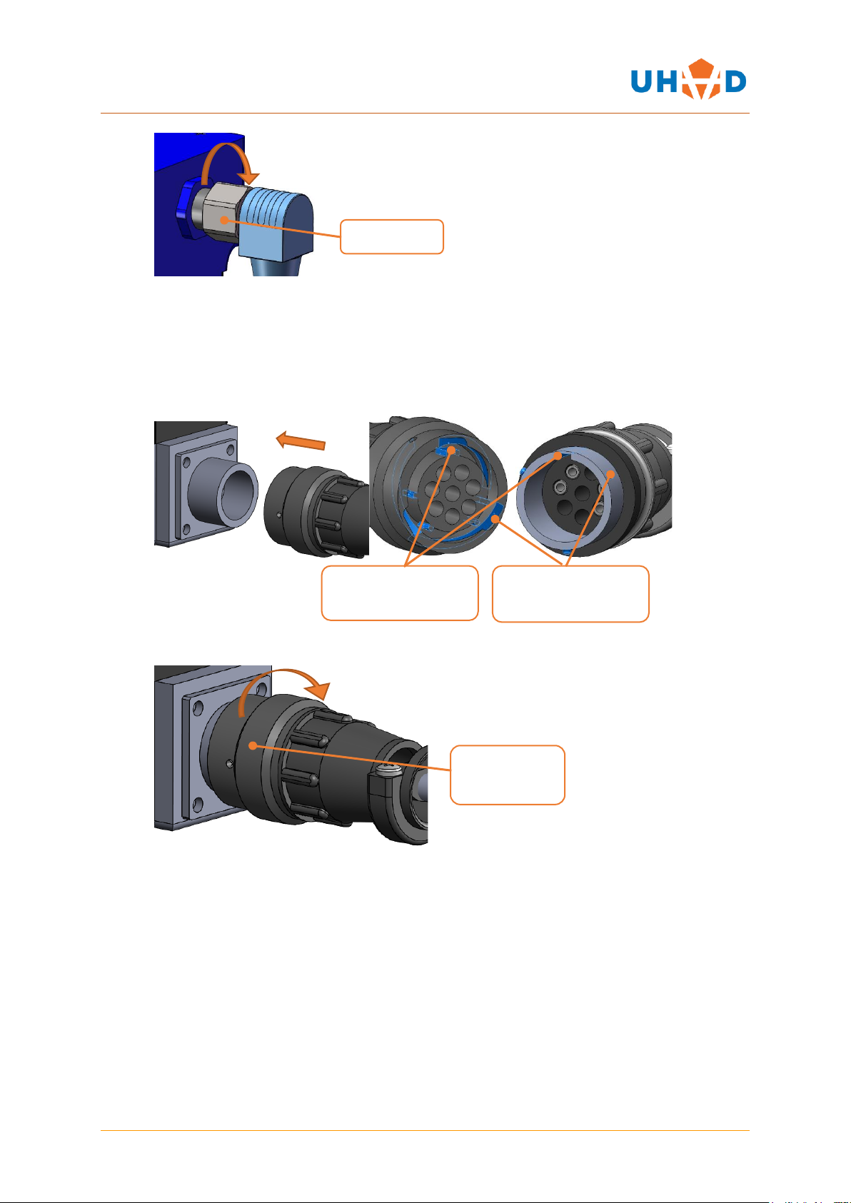
3.3.2 UTO Connectors
Older stepper motorised products use UTO style connectors on the motors. There is an adaptor cable
supplied with every motor cable to convert from the standard M12 connector to a UTO (part number
WD-C-006). To attach M12 cables together, see section 3.2.3
1. Push connector into socket. Note: socket will not engage unless key features are aligned
correctly on both the plug and locking ring
2. Twist the knurled locking ring clockwise until it clicks. (approximately 30°)
Knurled Nut
Knurled
Locking Ring
Plug alignment key
and slot
Locking ring
locating key
Inhaltsverzeichnis


