
Unicont SPb PCH-205 Bedienungsanleitung

Unicont SPb Ltd
Power Supply/Automatic Battery Charger
PCH-205
Technical Documentation
(205-1-27062012)
St. Petersburg
2012

Unicont SPb Ltd Technical Documentation PCH-205
Page 2
Table of Contents
1.GENERAL DATA ............................................................................................................4
2.DELIVERY SET...............................................................................................................4
3.SPECIFICATIONS ..........................................................................................................6
4.SAFETY ENGINEERING INSTRUCTIONS ...............................................................7
5.OPERATION PRINCIPLE .............................................................................................8
6.CONTROLS AND INDICATORS..................................................................................9
7.INSTALLATION AND CONNECTION......................................................................14
8.ALARM SIGNALS OF PCH-205 .................................................................................19
9.TRANSPORTATION AND STORAGE ......................................................................20
10.RECYCLING ..................................................................................................................21
11.WARRANTY ..................................................................................................................22
12.DATE OF PACKING.....................................................................................................23
13.ACCEPTANCE DETAILS ............................................................................................23
14.DATE OF COMMISSIONING .....................................................................................23

Unicont SPb Ltd Technical Documentation PCH-205
Page 3
This Operating Manual applies to the PCH-205 Power Supply/Automatic Battery
Charger.
This Manual is intended to assist in the familiarization with the design, operating
principles and procedures established for the convection heater during its intended use or
maintenance. This Manual can also be used as a source of information about сведений об
устройстве to draw up corresponding sections in the operational documentation for the
equipment, вкоторой this product may be used as its component part.
All information contained in this Manual is distributed by the company for information
purposes only. The information is subject to changes without notification to consumers; the
information may contain errors or discrepancies. The information provided may not contain
obligations on the part of Unicont SPb Ltd

Unicont SPb Ltd Technical Documentation PCH-205
Page 4
1. General data
A power Supply/Automatic Battery Charger PCH-205 (hereinafter referred to as — PS,
device) is designed to provide devices of the shipboard equipment with constant voltage 24 V.
Also, the device operates as a charging device (hereinafter referred to as — CHD) and
carries out automatic charging of storage batteries connected to it (hereinafter referred to as —
SB).
The PS is designed for operation at sea and river vessels in dry personnel facilities of
the house, superstructures or enclosed decks.
The operator’s manual (OM) describes PS design and operation principles, installation,
setting, and operation instructions.
The OM is designed for PS installation and setting specialists and PS users. To install
the PS, an appropriate electrical safety group is required.
2. Delivery Set
1. Combined power supply/charging device PCH-205 1 ps.
2. Operator’s manual 1 ps.
The following devices can be used additionally (optionally) with this product:
1. Control panel of storage batteries BCP-136
2. Alarm unit AU-106
3. Temperature sensor of storage battery DTS-135
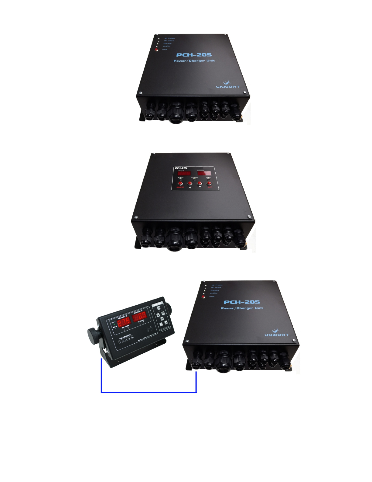
The PS is delivered in the following configurations (see Table 1):
Table 1. Device Configurations
Configuration Control and Management Functions
Base
(see Figure 1)
-LED indication of an operation mode
-Integrated audio and light alarm
-Alarm signal acknowledgement button
With integrated
control
(see Figure 2)
-Button keyboard of SB current and charging voltage control
-Digital indicator of SB current and charging voltage
-LED indication of an operation mode
-Integrated audio and light alarm
-Alarm signal acknowledgement button
With remote
control
(see Figure 3)
-Remote unit of set point value input of SB charge (with SB control
panel ВСР-136)
-Digital indicator of SB current and charging voltage
-LED indication of an operation mode
-Integrated audio and light alarm
-Remote audio and light alarm (as a part of SB control panel ВСР-136)
-Alarm signal acknowledgement button
Unicont SPb Ltd Technical Documentation PCH-205
Page 5
Figure 1. Base Configuration PCH-205
Figure 2. Configuration PCH-205 with Integrated Control
Figure 3. Configuration PCH-205 with Remote Control

Unicont SPb Ltd Technical Documentation PCH-205
Page 6
3. Specifications
Table 2. Electrical Specifications
Parameter Integrated Power Supply Unit Integrated
Charging Device
Supply Voltage 220 V (180 V ... 264 V), 50/60 Hz,
optionally: 110 V (90 V – 132 V), 50/60 Hz
Output Voltage 24 V, constant (direct current) 9–30 V (is selected by the operator),
in base configuration 28.4 V
Output Current 40 A 0.2–20.0 А(is selected by the operator),
in base configuration 20 A
Nominal Power 1,000 W 600 W
Connected SB: - 24 V, up to 200 A*h
12 V, up to 200 A*h
SB Charging Time - maximum 10 hours up to 80% of
capacity
A Number of
Terminals for
Connection of Loads
7 ps. (see Figure 9) 1 ps. (for connection of SB)
Integrated
Protections:
-galvanic separation of output supply from the supply main
-connection of SB with reverse polarity
-protection of the battery against deep discharge (a deactivated function)
-overheat protection of PS, CHD
-overheat protection of SB (when using a temperature sensor DTS-135)
Controls Keyboard, digital indicator, LEDs, power supply switch (the content of
controls depends on the device configuration, see para. 6)
Indicators Digital indicator, PS state indication LEDs (the content of indictors depends on
the device configuration, see para. 6)
Alarm Signals
-lack (failure) of supply voltage
-excess of the specified limits of SB charging current or voltage
-lack of SB connection (SB open-circuit failure, connection of SB with
reverse polarity, short circuit in the SB circuit)
-discharge of SB
Types of Alarm
Signals
Integrated Alarm:
-voltage-free (potential-free) relay contacts
-audio signal
-red LED
External Alarm (with devices):
-alarm unit AU-106
-panel control of storage batteries BCP-136

Unicont SPb Ltd Technical Documentation PCH-205
Page 7
Parameter Integrated Power Supply Unit Integrated
Charging Device
Performance 85 %
Overall Dimensions 370 mm × 350 mm × 140mm
Operating
Temperature: -20 °C …+55 °C
Storage Temperature -60 °C …+70 °C
Weight 9.65 kg
Protection Class IP 22
4. Safety engineering Instructions
IMPORTANT! Do not allow contact of the device with water and water penetration
into the device.
IMPORTANT! When cleaning the device surface, do not use organic solvents to avoid
damage of the applied symbols and inscriptions.
It is prohibited to:
-allow tension of the cables connected to the PS;
-connect the PS to the networks with parameters that differ from specified in the
manual;
-use the device for purposes other than that intended;
-operate a defective device.
Unicont SPb Ltd Technical Documentation PCH-205
Page 8
5. Operation principle
The device consists of two main modules: a power supply unit and charging device.
The modules are autonomous from each other and connected with a switching unit (relay)
between each other.
The switching unit, where there is supply voltage, connects load to the power supply
unit, and in case of supply voltage failure automatically switches the load to supply from the SB.
When restoring supply voltage, the switching unit automatically switches the load to supply
from the power supply unit, and charge of SB is resumed in automatic mode.
Thus, the device allows automatic charge of the storage batteries connected to it and
simultaneously provides output DC voltage 24 V to power the load.
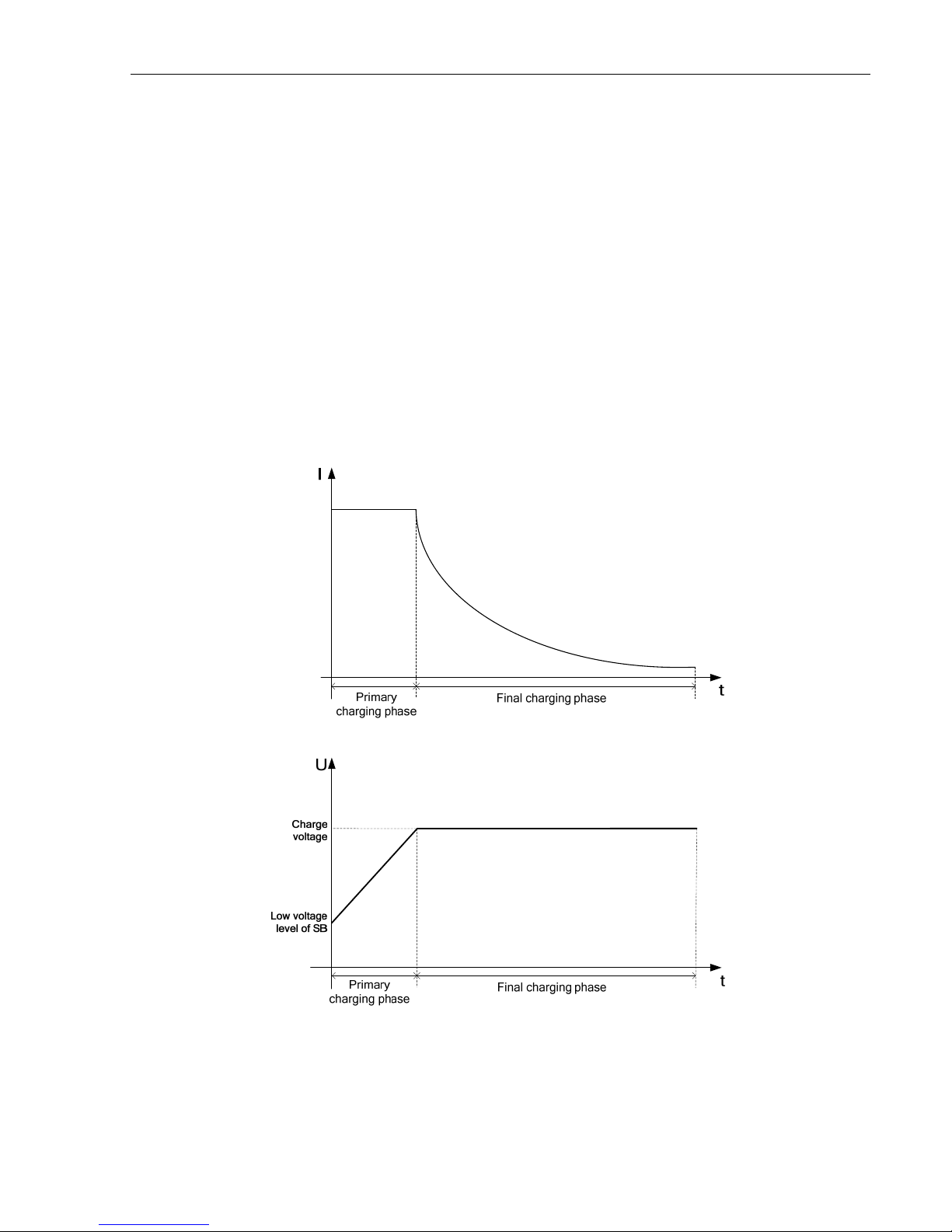
The battery is charged with a mixed method (operation in current regulation mode in
the primary charging phase with switching to voltage regulation mode in the final phase). The
curves of charging current and voltage of PS are given in the diagrams (see Figure 4):
Figure 4. Curves of Charging Current and Voltage of CHD
Unicont SPb Ltd Technical Documentation PCH-205
Page 9
6. Controls and indicators
The content of controls and indicators depends on the device configuration:
-for configuration of the devices of base and with remote control, a basic set of
controls and indicators is used (see para. 6.1);
-for configuration of the device with integrated control, an extended content of the
controls and indicators is used (see para. 6.2).
6.1 Basic Set of Controls and Indicators
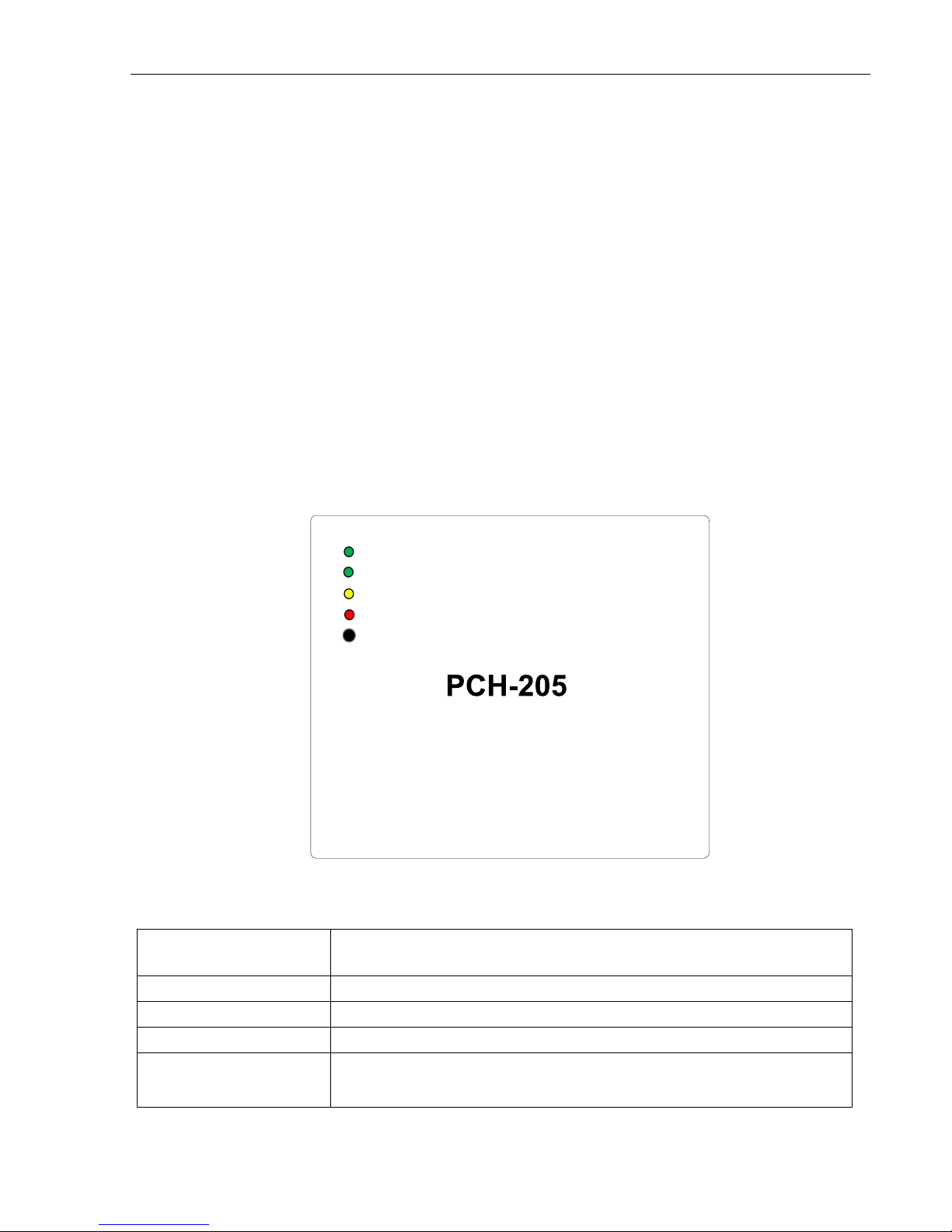
The basic device configuration includes the following controls and indicators: four
LEDs indicating PS state and operation mode (see Figure 5) and an audio alarm
acknowledgement button.
1. LEDs “AC Present”, “DC Output”, “Charging”, “ALARM” – are designed to
indicate current operation mode (see Figure 5, Table 3).
2. Button “Mute” is designed to switch off audio alarm, and light alarm will be
activated until the cause of alarm actuation is eliminated.
AC Present
DC Output
Charging
ALARM
Mute
Power / Charger Unit
Figure 5. Location of Controls and Indicators
Table 3. Purpose of LED Indicators
LED Indicator Purpose
AC Present (green) Flashes, where there is input supply 220 V
DC Output (green) Flashes, where there is output supply 24 V
Charging (green) Flashes while charging SB.
ALARM (red) Flashes in case of abnormal operation mode of the device (abnormal
operation modes, Table 8).
Unicont SPb Ltd Technical Documentation PCH-205
Page 10
6.2 Extended Set of Controls and Indicators
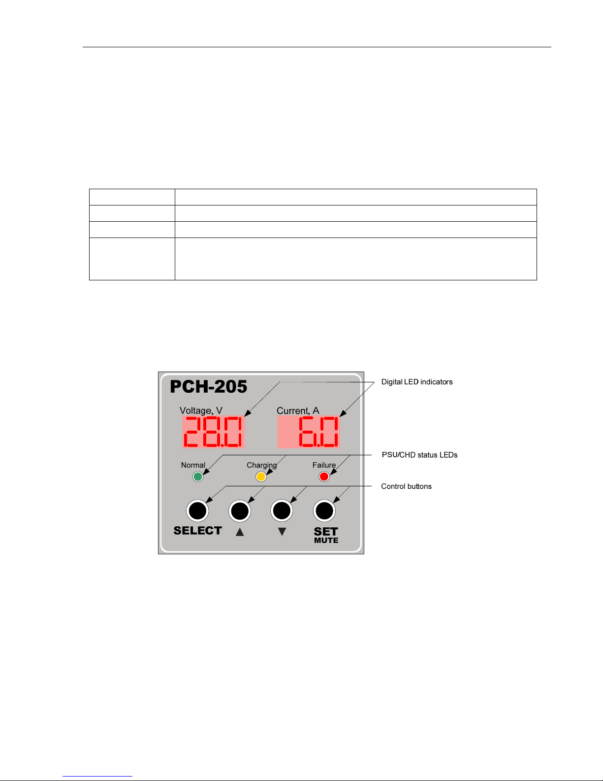
The device configuration with integrated control provides the following controls and
indicators: control buttons, three LEDs indicating the device state and operation mode, two
digital LED indicators (see Figure 6).
1. Control buttons are designed to set the device and acknowledge audio alarm (see
Purpose of the Buttons, Table 4).
Table 4. Purpose of Control Buttons
Button Purpose
“SELECT” Main menu option select button
“▲” and “▼” Parameter value select button
“SET/Mute”
Confirmation/preservation button of the selected value of the appropriate
parameter and switching off (acknowledgement) of audio signal at switched
on audio alarm
2. Digital LED indicators are designed to display current values of SB charging current
and voltage.
3. LEDs Failure, Normal, Charging are designed to indicate current operation mode of
PS. (See Figure 6, Table 5).
Figure 6 Location of PS Controls and Indicators with Integrated Control
Inhaltsverzeichnis
Andere Unicont SPb Stromversorgung Handbücher


