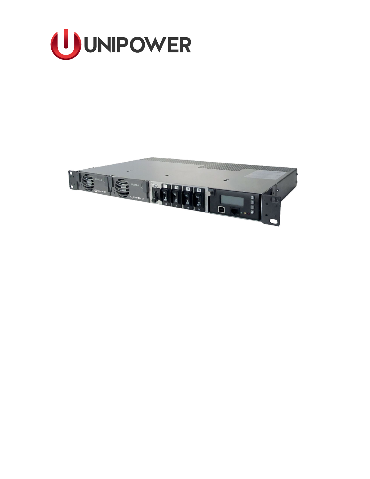
Unipower Aspiro 1U Bedienungsanleitung

Page 2
POWERING TECHNOLOGY
Document No. M00035-MAN rev. 3a
aspiro1u_m35-man-rev3a-0417.indd
Copyright © 1999-2017 UNIPOWER LLC
All Rights Reserved
Restricted Rights Legend:
Use, duplication, or disclosure by the Government is subject to restrictions as set forth in
subparagraph © (1)(ii) of the Rights in Technical Data and Computer Software clause at DFARS
252.227-7013 or subparagraphs © (1) and (2) of Commercial Computer Software - Restricted
Rights at 48 CFR 52.227-19, as applicable.
For Contact Information, please go to http://www.unipowerco.com/contact/
Refer to the UNIPOWER License Agreement in this package before installing or using this product.
Unless specically noted, all addresses, data characters and persons referenced herein, and all
examples involving names of companies and products, are ctitious examples and are designed
solely to illustrate the use of UNIPOWER products.
Product names, logos, brands, and other trademarks featured or referred to within this product
manual are the property of their respective trademark holders. These trademark holders are not
aliated with UNIPOWER LLC or our products. They do not sponsor or endorse our products.
LIMITATIONS AND AUTHORIZATIONS FOR USE AND PERMITTED APPLICATIONS
UNIPOWER’s products are not designed, intended for use in, or authorized for use as critical
components in, human life support systems/equipment, equipment used in hazardous environments,
or equipment used in nuclear control equipment or systems. Any such use requires the prior
express written consent of an authorized executive ocer of UNIPOWER LLC, which consent
may be withheld by UNIPOWER LLC in its sole discretion. Users assume all risk and liability for,
and agree to indemnify and defend UNIPOWER from and against any claims for personal injury
(including death) or property damage resulting from any such use or application which is made in
the absence of such prior express written consent.
If you nd errors or problems with this documentation, please notify UNIPOWER. UNIPOWER
does not guarantee that this document is error-free. The information in this document is subject to
change without notice.

Page 3
POWERING TECHNOLOGY
Document No. M00035-MAN rev. 3a
aspiro1u_m35-man-rev3a-0417.indd
Contents
Chapter 1 About This Manual
1.1 Objectives ..................................................................................................................................6
1.2 Audience ....................................................................................................................................6
1.3 Document Key ...........................................................................................................................6
1.4 Feedback & Support ..................................................................................................................7
1.6 Disclaimer..................................................................................................................................7
Chapter 2 Aspiro System Description
2.1 Overview....................................................................................................................................8
2.2 System Congurations...............................................................................................................8
2.3 System Parameters.....................................................................................................................9
2.4 System Components.................................................................................................................11
2.4.1 System Controller ...........................................................................................................11
2.4.2 DC Distribution...............................................................................................................11
2.4.4 Rectier Module .............................................................................................................12
Chapter 3 System Safety
3.1 Safety Warnings and Guidelines ..............................................................................................13
3.1.1 System Markings ............................................................................................................13
3.1.2 Safety Recommendations................................................................................................13
3.1.3 Installation Warning........................................................................................................14
3.1.4 Restricted Access Area Warnings....................................................................................14
3.1.5 Electrical and Fire Enclosure..........................................................................................14
3.1.6 System Enclosure............................................................................................................14
3.1.7 Operating Temperature Warnings ...................................................................................14
3.1.8 Electrical Safety Warnings..............................................................................................14
3.1.9 Grounding .......................................................................................................................15
3.1.10 Batteries ........................................................................................................................16
3.1.10.1 Lead Acid Batteries ........................................................................................16
3.1.11 In Case of an Accident ..................................................................................................16
3.2 Caution.....................................................................................................................................17
3.2.1 Storage and Transportation .............................................................................................17
3.2.2 Disposal...........................................................................................................................17
3.2.3 Handling Electrostatic Sensitive Devices .......................................................................17
3.2.4 Traceability .....................................................................................................................17
3.2.5 Breakers ..........................................................................................................................17
3.2.5.1 Circuit Breaker Limitations .............................................................................17

Page 4
POWERING TECHNOLOGY
Document No. M00035-MAN rev. 3a
aspiro1u_m35-man-rev3a-0417.indd
Chapter 4 Installation Guide
4.1 Introduction..............................................................................................................................19
4.2 Unpacking................................................................................................................................19
4.3 Tools 19
4.4 Rack Mounting.........................................................................................................................19
4.5 Rear Connections.....................................................................................................................21
4.5.1 DC Earth Connection (FRAME GROUND) ..................................................................21
4.5.2 Mains Connection ...........................................................................................................22
4.5.3 Alarm and Signal Connections........................................................................................23
4.5.4 DC Load Connections.....................................................................................................25
4.5.5 Battery Connections .......................................................................................................26
4.5.6 Symmetry Connection ....................................................................................................27
4.5.7 Temperature Sensor Connection .....................................................................................28
Chapter 5 Commissioning
5.1 Commissioning Overview .......................................................................................................29
5.2 Tools and Test Equipment........................................................................................................29
5.2.1 Tools List.........................................................................................................................29
5.2.2 Test Equipment ...............................................................................................................29
5.3 Preparation ...............................................................................................................................29
5.4 Commissioning procedure .......................................................................................................30
5.5 Test of output voltage...............................................................................................................31
5.5.1 Float charge (U1) ............................................................................................................31
5.5.2 Adjustment of Float Charge, U1 .....................................................................................31
5.5.3 Boost charging (U2) (if applicable) ................................................................................31
5.6 Battery supervision ..................................................................................................................32
5.7 Battery test ...............................................................................................................................32
5.8 Commissioning record.............................................................................................................33
Chapter 6 Maintenance & Troubleshooting
6.1 Maintenance.............................................................................................................................34
6.2 Troubleshooting .......................................................................................................................34
Chapter 7 Replacing Modules
7.1 Controller Replacement ...........................................................................................................38
7.2 Rectier Replacement..............................................................................................................39
7.2.1 XR04.48 / XR08.48 Replacement ..................................................................................39
7.2.2 XPGe12.48 Replacement................................................................................................39
7.3 Breaker Replacement ...............................................................................................................40
Appendix A - Block Diagram ......................................................................................................42
Appendix B - CSA Certicate Extract .......................................................................................43
Appendix C - Revision History ...................................................................................................44

Page 5
POWERING TECHNOLOGY
Document No. M00035-MAN rev. 3a
aspiro1u_m35-man-rev3a-0417.indd
FIGURES
Figure 2-1 Power System Overview ...........................................................................................8
Figure 2-2 XPGe12.48 and XR04.48/XR08.48 ........................................................................12
Figure 4-1 Dimensional Drawing (Front and Top View) ..........................................................20
Figure 4-2 System Mounting (19” mount)................................................................................20
Figure 4-3 Rear Connections.....................................................................................................21
Figure 4-4 DC Earth Connections.............................................................................................21
Figure 4-5 Mains Connection (viewed from rear).....................................................................22
Figure 4-6 Mains Connection Detail.........................................................................................23
Figure 4-7 Signal Pin Designations...........................................................................................24
Figure 4-8 Signal Connection Detail.........................................................................................25
Figure 4-9 Load and Battery Connections (Rear View)............................................................25
Figure 4-10 Signal Connection Detail.........................................................................................26
Figure 4-11 2-block Symmetry Measurement (for illustration only)..........................................27
Figure 4-12 4-Block Symmetry Measurement (for illustration only) .........................................27
Figure 4-13 Temperature Sensor Connection..............................................................................28
Figure 7-1 Unlocking the Controller.........................................................................................38
Figure 7-2 Removing the Controller .........................................................................................38
Figure 7-3 Replacing an XR04.48 or XR08.48 Rectier..........................................................39
Figure 7-3 Replacing an XPGe12.48 Rectier..........................................................................40
Figure 7-5 Top Cover Removal.................................................................................................40
Figure 7-6 Breaker Removal - A ...............................................................................................41
Figure 7-7 Breaker Removal - B ...............................................................................................41
TABLES
Table 4-1 Recommended Mains Circuit Protection.................................................................22
Table 4-2 Cable Sizes ..............................................................................................................26
Table 4-3 Cable Sizes ..............................................................................................................27
Table 5-1 Float/Boost Charge Voltages ...................................................................................31
Table 5-2 Commissioning Record ...........................................................................................33

Page 6
POWERING TECHNOLOGY
Document No. M00035-MAN rev. 3a
aspiro1u_m35-man-rev3a-0417.indd
1. About This Manual
This chapter contains an overview of the information that is presented in this Power System
Manual. This includes information on objectives, the intended audience, and the organization
of this manual. In addition, this chapter also denes the conventions used to indicate warnings,
cautions and noteworthy information.
1.1 Objectives
This manual describes the Power System, explains how to unpack and install the system,
how to perform the initial power-up and operational system check.
The information presented in this document is current as of the publication date.
1.2 Audience
This manual is to be used by installers and technicians who are preparing the site for a new
installation and installing the power system. This manual assumes that the technician has an
understanding of power systems in general and understands safety procedures for working
around AC and DC voltage.
The user of this document should be familiar with electronic circuitry and wiring practices
and have some expertise as an electronic, power, or electromechanical technician.
1.3 Document Key
This manual uses the following conventions:
WARNING This symbol indicates a situation that could cause bodily injury. Always
be aware of hazardous conditions when working in or around the power system.
CAUTION This symbol indicates a situation that might result in equipment damage.
The reader should be aware that their actions could result in equipment or data
loss.
NEED MORE INFORMATION? This symbol is used to reference information
either in this manual or in another document.
NOTE This symbol means the reader should take note. Notes are helpful
suggestions or reminders.
Chapter 1 About This Manual

Page 7
POWERING TECHNOLOGY
Document No. M00035-MAN rev. 3a
aspiro1u_m35-man-rev3a-0417.indd
Table 1-1 Abbreviations
Abbreviation Description
PCC Prime Controller Card
ACC Advance Controller Card
LVD Low Voltage Disconnection
PLD Partial Load Disconnection
XR04.48 400 W Rectier
XR08.48 800 W Rectier
XPGe12.48 1200 W Rectier
DB22 Distribution Drawer (4 x load, 1 x battery)
D22 Distribution Drawer (3 x load)
D33 Distribution Drawer 2 x load)
B33 Distribution Drawer (2 x battery)
1.4 Feedback & Support
For technical support or feedback, please visit http://www.unipowerco.com/contact/ for
details.
1.5 Layout, Numbering and Printing
This manual is intended for two-sided black and white printing. Some pages are intentionally
left blank.
1.6 Disclaimer
UNIPOWER is not responsible for system problems that are the result of installation or
modication of the instructions provided in this manual.

Page 8
POWERING TECHNOLOGY
Document No. M00035-MAN rev. 3a
aspiro1u_m35-man-rev3a-0417.indd
2.1 Overview
Aspiro DC power systems oer a range of solutions for diverse applications such as broadband
access, cable head ends, micro/pico BTS Cells, Enterprise, E911, and GSM-R.
The Aspiro shelf system utilizes ecient, dense, and reliable plug-in rectier modules
XR04.48, XR08.48 or XPGe12.48, with output power available at either 400W, 800W or
1200W per rectier, based upon a soft-switching approach. Features include wide input
operating range, wide operating temperature, full self-protection and three LEDs for
immediate rectier status indication.
The power system can be managed locally through messages and alarm displayed on the
LCD screen of the system controller or remotely, using the PC-based PowCom™ software,
or through a web browser with Ethernet connection.
2.2 System Congurations
Aspiro 1U system consists of:
1. System Controller ACC Extended
2. 4 x Load and 1 x Battery breakers including LVD
3. XR04.48 / XR08.48 / XPGe12.48 Rectiers (Maximum 2)
4. Rear Connections
1
2
3
4
Figure 2-1 Power System Overview
Chapter 2 Aspiro System Description

Page 9
POWERING TECHNOLOGY
Document No. M00035-MAN rev. 3a
aspiro1u_m35-man-rev3a-0417.indd
2.3 System Parameters
OUTPUT
Power (max) 2400W @ >180VAC, 800W @ <180VAC
Output Current 52A max. @ 46VDC, 45A nominal (see appendix B)
15A (Low Power Shelf version with 20A shunt)
Voltage 46-57VDC
INPUT
Voltage 85-275VAC (Single-phase, 2 x Single-phase)
Frequency 50-60Hz
Input Current 16A (Single-phase), 8A (2 x Single-phase)
Power factor >0.98
DC DISTRIBUTION
Battery Breakers 1 x (AIRPAX, IER Series)
Ratings 40A, 50A, 65A
Load Breakers 4 x (NADER NDB3 Series)
Ratings* 1A, 4A, 5A, 7.5A, 10A, 15A, 20A, 25A, 30A
MONITORING AND CONTROL
Controller PCC or ACC Extended
Local Interface 4 x 20’ LCD, 4-key menu, USB (ACC only) and RS232
Remote Interface Ethernet / Modem using PowCom™ software
Visual Indication Green LED - System On
Yellow LED - Message(s)
Red LED - Alarm(s)
Analog Inputs 12 x voltage inputs (range 0-100VDC) - used for symmetry inputs
Analog Outputs 4 x potential free relays (C, NC, NO)
Digital Inputs 2 x, Logic 0: U<10VDC, Logic 1: U>12VDC
Digital Outputs 2 x, open collector type
Temperature measurement 2 x Temperature probe (Battery, Ambient)
CONNECTIONS
Battery connections Stripped cable, max.16mm2, spring type connector
AC connections Stripped cable with ferule, max. 2.5mm2, screw type connector
Load breaker connections Stripped cable with ferule, max. 4mm2, screw type connector
Alarm connections Stripped cable with ferule, max. 1.5mm2, screw type connector
* For load breaker derating limitations see chapter 3.2.5 Breakers on page 3-6.

Page 10
POWERING TECHNOLOGY
Document No. M00035-MAN rev. 3a
aspiro1u_m35-man-rev3a-0417.indd
RECTIFIER MODEL XPGe12.48 XR08.48 XR04.48
Eciency 95% typical @ Iout nom 90% typical @ Iout nom 88% typical @ Iout nom
Input Current (max) <7.3A <10.5A <5.3A
Output Current (max)
53.5V oat
22.4A 15.0A 7.5A
Output Power 1200W @ >180VAC
750W @ 90-180VAC
800W 400W
Operating Temperature
(without derating)
55°C 65°C 65°C
Input Voltage
(Nominal 100-240VAC)
90-300VAC 85-300VAC
Output Voltage 46-57VDC
Load sharing < 5% of nominal current
Dimensions (WxHxD) 40.6 (1.6”) x 101.62(4”) x 228.5(9”) mm
Weight 1.1 kg
Cooling Fan-cooled, speed and alarm controlled, air ow direction rear to front
Protection Short circuit proof, automatic current limiting, selective shutdown of modules at
excessive output voltage.
Alarms High output voltage/ shutdown, Low voltage/ module failure
LED Indication Green: Power ON
Yellow: Current limit/ thermal protection
Fan failure / Over temperature
Pre-warning / thermal protection
Communication Failure (ashing)
Red: Module failure / high output voltage shutdown
Audible noise <55dBA according to ISO7779
MECHANICAL
Dimensions (WxHxD) 480 mm x 44.45 mm x 266 mm
Weight of the system
(fully equipped)
6.5 kg
Mounting Options 19”/ ETSI / Mid-mount
Cable Entry Rear Access
STANDARD COMPLIANCE / ENVIRONMENTAL
EMC and Immunity ETSI EN 300 386 V.1.5
EN 55022
EN 55024, EN 61000-4
Safety EN 60950-1
Operating Temperature -40°C to +75°C, derating over +47°C (see appendix B)
Storage Temperature -40°C to +85°C
Andere Handbücher für Aspiro 1U
1
Dieses Handbuch passt für folgende Modelle
3
Inhaltsverzeichnis
Andere Unipower Stromversorgung Handbücher

Unipower
Unipower Guardian Access 3U Bedienungsanleitung

Unipower
Unipower Gravitas X100 Bedienungsanleitung

Unipower
Unipower Gravitas X100 Montageanleitung

Unipower
Unipower ARE Series Bedienungsanleitung

Unipower
Unipower Aspiro 1U Enclosure Bedienungsanleitung

Unipower
Unipower Guardian Access Bedienungsanleitung

Unipower
Unipower XPGe12.48 Bedienungsanleitung

Unipower
Unipower Aspiro 1UMS22 Bedienungsanleitung

Unipower
Unipower TMN6000 Bedienungsanleitung

Unipower
Unipower Bluestrak Series Bedienungsanleitung