Upgrading everyday security iconnect Bedienungsanleitung

Quick Start Installation Guide
For detailed information please refer to the full iConnect
Installer Manual provided on our website: www.electronics-line.com

2
Table of Contents
1. Introduction ............................................................................................................3
2. System Installation ................................................................................................3
3. System Layout........................................................................................................4
3.1. System Architecture...............................................................................4
3.2. Hardware Layout .....................................................................................5
3.2.1. Main Board .................................................................................................6
4. System Programming ............................................................................................8
4.1. Keys Menu Navigation ...........................................................................8
4.2. Enter Installer Programming mode....................................................8
4.3. Selecting a language..............................................................................8
4.4. Wireless Allocation .................................................................................8
4.4.1. Main unit calibration ...................................................................................8
4.4.2. Registering 2-way Wireless Devices ..........................................................9
4.4.2.1. Detectors ....................................................................................................9
4.4.2.2. Keyfobs ....................................................................................................11
4.4.2.3. Wireless LCD keypads.............................................................................12
4.4.2.4. Wireless Siren ..........................................................................................13
4.4.3. Delete Wireless Device ............................................................................13
4.5. Program Communication to Monitoring Station ..........................15
4.6. Set Up Follow Me Destination ...........................................................16
4.7. Set Time & Date.....................................................................................17
4.8. Set/Edit Users .........................................................................................18
4.9. GPRS Settings.........................................................................................20
4.10. Connect to ELAS (GPRS / LAN Configurations) .......................21
4.11. PIR Camera .........................................................................................22
5. Testing the System ..............................................................................................23

3
1. Introduction
Thank you for choosing iConnect wireless intruder control panel. This quick start
guide manual describes the main steps for installing and programming the iConnect
Control System using the keypad on the main unit.
2. System Installation
1. Open the main unit housing.
. Place the rear main unit against the wall and mark the upper and lower
mounting holes.
Note
If required, mark the rear tampers' location. It is located behind the main board.
3. Install wall anchors in the appropriate positions
4. Thread the power cable through the wiring hole on the back cover and connect
the cable to the AC power input on the main board.
Caution
Do not apply AC power at this stage.
5. If required connect a network (IP) cable and/or insert a SIM card to the
GSM/GPRS module.
6. Connect the battery pack to the connector. If an alarm occurs, insert the master
user code number (default '1 34') to silence the alarm.
7. Mount the control system to a wall.
8. Close the front cover and apply AC power.
Note
It is recommended to perform a system scan in order to erify the system configuration. A
system scan is performed from the main menu: '[9] Programming' > '[7] Initialize' > '[5]
Find Modules' > '√'. The generated list displays the recognized system elements. If an
element is not included in the list, check the wiring connections and run this scan again.

4
3. System Layout
3.1. System Architecture
Figure 1 shows the components of the system and the systems' interaction with external
communication networks.
Figure 1: System Architecture
See Figure 2

5
Figure 2: Main board
Contrast LCD
Speaker
Bell
Jumper for siren volume
Flat Cable

6
3.2. Hardware Layout
The aim of this section is to present the systems' various circuit boards (Figure 3). Apart
from the Main Board, each peripheral module is available as an additional desi ned
option to be installed inside the plastic housin .
Figure 3: System layout
Power and Connection board
Communication module (GPRS + GSM + LAN)
Backup battery pack
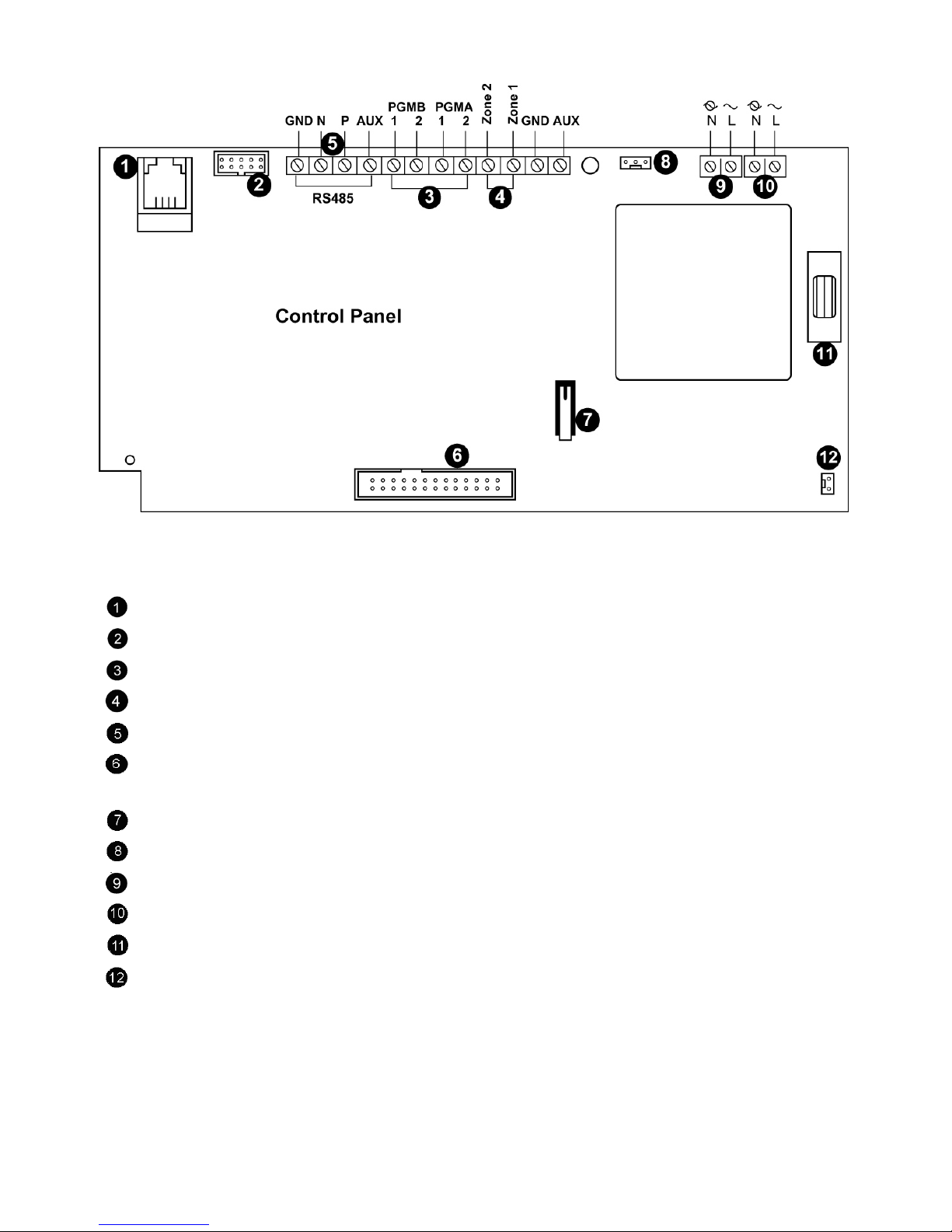
3.2.1. Power and Connection Board
The Power and Connection board is the system's main part and connects to various
peripheral modules usin a number of interface connectors as seen in Figure 5.
7
Figure 4: Power and Connection board
Interphone module connector
Flat-cable interface connector to communication module
Programmable relay output (100mA max. load
Wired detector zone (Zone 33, 34
System bus terminal block (hardwire LCD keypad, Wired Zone Module
Flat-cable interface connector to Main board (LCD keypad, built-in speaker,
microphone and siren
Front tamper switch
Interface connector to Home Automation module
AC power terminal block
Home Automation module terminal block
AC power protection fuse
Backup battery connector

8
4. System Programming
4.1. Keys Menu Navigation
This manual explains how to program the iConnect from the keypad located either on
the main unit or on the LCD wireless keypad. Table 1 describes using the keypad keys
during programming.
'√' Enter Save (to move into the displayed menu or to save the updated
data)
'X' Used to cancel the current selection or to return to the previous menu
To scroll up or down through the displayed menu options
[0]-[9] 1. To enter numeric values where required.
2. For quick key programming. Press the key number to access a
programming option.
3. To edit descriptors.
Table 1: Keypad usage
4.2. Enter Installer Programming mode
1. Go to the default display and press '√'.
2. Enter your installer code (default installer code is '1111').
3. Using the arrow keys, select '[9] Programming'.
4.3. Selecting a language
The iConnect supports multiple languages. For easy operation, select your language
as follows:
1. Go to the main menu select [9]>[7]>[1] (Programming > Initialize > Init All)
2. Select default and press '√'. Select language (Voice + LCD display) and press '√'.
4.4. Wireless Allocation
4.4.1. Main unit calibration
The first step in wireless allocation is to calibrate the main unit receiver. During the
calibration process the receiver selects the best RF channel according to the background
ʺnoiseʺ in the installation environment. This noise may be generated by other devices
operating on the same frequency nearby.
1. Go to the main menu select [9]>[1]>[8] >[1] (Programming > Devices > RF
Network > Establishment)
2. The iConnect scans several RF channels and selects the channel with lower
ʺnoise levelʺ. Once 'Save?' display appears, press '√' to confirm the channel
selection.

9
Notes
1. Main unit calibration must be done prior to wireless device allocation.
2. If required, after the channel is selected, you can calibrate the receiver again only after deleting
the network quick keys: [9]>[1]>[8] >[3])=
4.4.2. Registering 2-way Wireless Devices
In order to recognize a 2-way device, the iConnect transmitter must be registered.
It is recommended to register all devices to the control panel before installing. o install
the wireless devices/accessories temporarily fit them in the desired locations, and then
perform a range test. esting may show that you should relocate the panel or some of its
devices/accessories.
4.4.2.1.Detectors
he iConnect supports 34 security zones. Only one detector can be registered to each
zone. Zones 1-32 are intended for wireless detectors while zones 33 and 34 are on-board
hardwire zones.
Notes
1. The minimum distance between the detectors and the panel should be 1.5m.
2. Once a detector is deleted from the panel it must be followed by the deletion of the panel in the
detector. If this is not done, it will lead to an "out of Sync" situation by design
Step 1: Register a detector
1. Go to the main menu select [9]>[1]>[1] (Programming > Devices > Zones)
2. Using the arrow keys, select a specific zone and press '√'. he system initiates
Registration mode.
3. Send a transmission from the detector using the following method:
Open the detector's housing (tamper should be open)
Apply battery power. he detector will send a transmission. If the transmission
is successfully received by the system it will play a confirmation sound. If no
confirmation sound is heard send another transmission by pressing and
releasing the tamper switch of the device.
4. After the detector is successfully registered the display shows: 'Save?'.
Press '√' to confirm and continue entering other parameters for the chosen
device (see section below). It is possible to press 'X' to go back and enroll
additional zones.
Step 2: Set detector's parameters
1. Go to the main menu select [9]>[1]>[1] (Programming > Devices > Zones)
2. Using the arrow keys select a specific zone and press '√'.
3. Set the main parameters for each zone, according to the Table 2.

10
Quick Key Option Name Description and Notes
9>1>1>2 Zone Type Type of alarm this zone generates
9>1>1>3 Arm Set Arming methods in which the zone is included
1 (F): The zone is included in Full arming
2 (P): The zone is included in Part arming
3 (PE): The zone is included in Perimeter arming
9>1>1>4 Descriptor Descriptors help identify the device when the system is
being operated and programmed
9>1>1>5 Bell (Siren) Activate the siren when the zone is triggered
9>1>1>6 Chime Activate the internal siren when the zone is triggered
Note: To enable the chime option enable Global Chime
option [quick keys: 7>12]
9>1>1>7 Force Arm Arm the system even if a zone is not ready For the force
arm feature to function, you must also enable force
arming in system options
Table 2: Parameter settin s
Note
PIR and Camera PIR detector have dedicated parameters They can be defined using
quick key 9>1>1>11
4. If required scroll thorough the other menu parameters and modify settings as
warranted.
Step 3: Detectors Test
1. Go to the main display and press '√'.
2. Enter the installer code (default code '1111' .
3. Select [7]>[04]>[2] (Service > Transmitters > TX Test to initiate the TX
communication test. This test enables to identify transmitters and test their
signal strength.
4. Activate the transmitter you wish to test; the transmitter’s details appear on
the iConnect LCD. As a result, a sequence of tones is heard indicating the
transmitter’s signal strength.
Andere Handbücher für iconnect
1
Inhaltsverzeichnis
Andere Upgrading everyday security Sicherheitssystem Handbücher


Beliebte Sicherheitssystem Handbücher anderer Marken


EDM
EDM Solution 6+6 Wireless-AE Bedienungsanleitung

Highway Safety Group
Highway Safety Group EA401 Bedienungsanleitung

Siren
Siren LED GSM Bedienungsanleitung

Detection Systems
Detection Systems 7090i Montageanleitung

Se-Kure Controls
Se-Kure Controls MicroMini SK-4841 Bedienungsanleitung

Siemens
Siemens FDM273 Bedienungsanleitung