
V Robin 300 plasma spot Bedienungsanleitung

1
Version1.6

2
Table of contents
1. Safety instructions ......................................................................................................... 3
2. Operating determination................................................................................................ 4
3. Fixture exterior view ...................................................................................................... 5
4. Installation....................................................................................................................... 6
4.1 Placing the xture head covers ................................................................................. 6
4.2 Connection to the mains ............................................................................................ 6
4.3 Replacing the colour lters and gobos ...................................................................... 6
4.4 Rigging the xture ...................................................................................................... 8
4.5 DMX-512 connection................................................................................................ 10
4.6 Ethernet connection ................................................................................................. 11
5. Remotely controllable functions................................................................................. 13
6. Control menu map........................................................................................................ 14
7. Control menu ............................................................................................................... 17
7.1 Tab " Address" ......................................................................................................... 18
7.2 Tab "Information"...................................................................................................... 18
7.3 Tab "Personality"...................................................................................................... 20
7.4 Tab "Manual Control" ............................................................................................... 22
7.5 Tab "Stand-alone" ................................................................................................... 22
7.6 Tab "Service"............................................................................................................ 23
7.7 Icon "Lamp menu".................................................................................................... 25
8. RDM ............................................................................................................................... 25
9. Error and information messages ................................................................................ 26
10. Technical Specications............................................................................................ 27
11. Maintenance and cleaning......................................................................................... 29
Robin 300 Spot

3
CAUTION!
Keep this device away from rain and moisture!
Unplug mains lead before opening the housing!
FOR YOUR OWN SAFETY, PLEASE READ THIS USER MANUAL CAREFULLY
BEFORE YOU INITIAL START - UP!
1. Safety instructions
Every person involved with installation and maintenance of this device have to:
- be qualied
- follow the instructions of this manual
CAUTION!
Be careful with your operations.
With a high voltage you can suffer
a dangerous electric shock when touching the wires!
This device has left our premises in absolutely perfect condition. In order to maintain this condition and to en-
sure a safe operation, it is absolutely necessary for the user to follow the safety instructions and warning notes
written in this manual.
Important:
The manufacturer will not accept liability for any resulting damages caused by the non-observance of this
manual or any unauthorized modication to the device.
Please consider that damages caused by manual modications to the device are not subject to warranty.
Never let the power-cord come into contact with other cables! Handle the power cord and all connections with
the mains with particular caution!
Make sure that the available voltage is not higher than stated on the rear panel.
Always plug in the power plug least. Make sure that the power-switch is set to off-position before you connect
the device to the mains. The power plug has to be accessible after installing the device.
Make sure that the power-cord is never crimped or damaged by sharp edges. Check the device and the power-
cord from time to time.
Always disconnect from the mains, when the device is not in use or before cleaning it. Only handle the power-
cord by the plug. Never pull out the plug by tugging the power cord.
This device falls under protection class I. Therefore it is essential to connect the yellow/green conductor to
earth.
The electric connection, repairs and servicing must be carried out by a qualied employee.
Do not connect this device to a dimmer pack.
During the initial start-up some smoke or smell may arise. This is a normal process and does not necessarily
mean that the device is defective.
Do not touch the device’s housing bare hands during its operation (housing becomes hot)!
For replacement use lamps and fuses of same type and rating only.
CAUTION ! EYE DAMAGES !
Avoid looking directly into the light source
(meant especially for epileptics) !

4
2. Operating determination
This device is a moving head for creating decorative effects and was designed for indoor use only.
If the device has been exposed to drastic temperature uctuation (e.g. after transportation), do not switch it on
immediately. The arising condensation water might damage your device. Leave the device switched off until
it has reached room temperature.
Do not shake the device. Avoid brute force when installing or operating the device.
Never lift the xture by holding it at the projector-head, as the mechanics may be damaged. Always hold the
xture at the transport handles.
When choosing the installation-spot, please make sure that the device is not exposed to extreme heat, moisture
or dust. There should not be any cables lying around. You endanger your own and the safety of others!
The minimum distance between light output and the illuminated surface must be more than 1.5 meters.
Make sure that the area below the installation place is blocked when rigging, derigging or servicing the x-
ture.
Always x the xture with an appropriate safety rope. Fix the safety rope at the correct hole only.
Only operate the xture after having checked that the housing is rmly closed and all screws are tightly fas-
tened.
The maximum ambient temperature 40°C must never be exceeded.
CAUTION!
The lens has to be replaced when it is obviously damaged,
so that its function is impaired, e. g. due to cracks or deep scratches!
Operate the device only after having familiarized with its functions. Do not permit operation by persons not
qualied for operating the device. Most damages are the result of unprofessional operation!
Please use the original packaging if the device is to be transported.
Please consider that unauthorized modications on the device are forbidden due to safety reasons!
If this device will be operated in any way different to the one described in this manual, the product may suffer
damages and the guarantee becomes void. Furthermore, any other operation may lead to dangers like short-
circuit, burns, electric shock etc.

5
3. Fixture exterior view
Rear panel of the base:
1 - Ethernet input-RJ45
2 - 3-pin DMX output
3 - 5-pin DMX output
4 - Fuse holder-neutral
5 - Fuse holder-live
6 - Power switch
7 - 3-pin DMX input
8 - 5-pin DMX input
9 - Power cord
Front panel of the base:
1 - QVGA touch screen
2 - ESCAPE button
3 - NEXT button
4 - ENTER/DISPLAY ON button
5 - PREV button
The head should be locked for transportation- the tilt lock latch (2) and the pan lock latch (3) have to be in the
locked positions. To unlock the head, move these latches to unlock positions before operating the xture.
1 - Front lens
2 - Tilt lock
3 - Pan lock
4 - Base
5 - Moving head
6 - Arm
The ENTER/DISPLAY ON button also serves for switching the display on when the xture is disconnected
from the mains.

6
4. Installation
Fixtures must be installed by a Qualied electrician in accordance with all
national and local electrical and construction codes and regulation.
4.1 Placing the xture head covers
The plastic head covers cannot be interchanged otherwise the xture head will by overheated and the light
source will be switched off. The rectangular array of air vents has to be over two axial fans.
Pay attention to correct placing the covers on the head according to the following drawing:
4.2 Connection to the mains
For protection from electric shock, the xture must be earthed!
The Robin 300 Plasma Plasma Spot is equipped with auto-switching power supply that automatically adjusts
to any 50/60Hz AC power source from 100-240 Volts.
Install a suitable plug on the power cord, note that the cores in the power cord are coloured according to the
following table. The earth has to be connected!
If you have any doubts about proper installation, consult a qualied electrician.
Core (EU) Core (US) Connection Plug Terminal Marking
Brown Black Live L
Light blue White Neutral N
Yellow/Green Green Earth
4.3 Replacing the colour lters and gobos
DANGER!
Install the colour lters or gobos with the device switched off only.
Unplug from mains before!
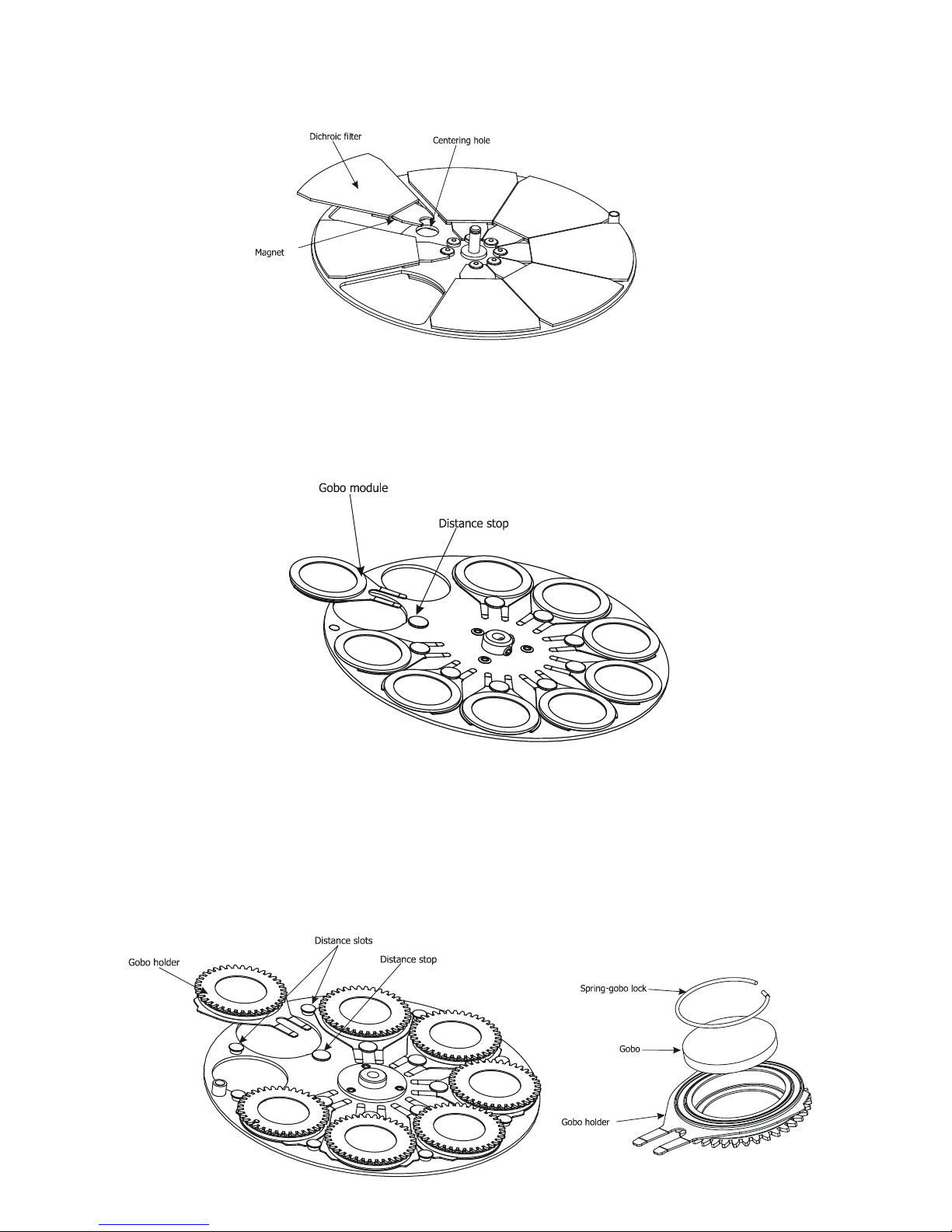
Colour lters
1. Disconnect the xture from mains and allow it to cool.
2. Remove the top plastic cover of the head by loosening the 4 quarter-turn fasteners on the cover.
3. Turn the colour wheel to the desired position.The dichroic lters are xed on the colour wheel by the
magnets.
7
4. Release the dichroic lter from the colour wheel by inclining it from its position
to break the power of the magnet
. Protect the glass lter with a piece of paper or clout.
5. Insert a new dichroic lter into the colour wheel.
6. Place the top cover back before applying power.
Static gobos
1. Disconnect the xture from mains and allow it to cool.
2. Remove the top plastic cover of the head by loosening the 4 quarter-turn fasteners on the cover.
3. Gently skew the gobo module to release it from the hole in the static gobo wheel and
pull it up.
4. Insert the new gobo module spring holder under the distance stop and push the gobo module into hole in
the static gobo wheel
.
5. Replace the top cover before applying power.
Rotating gobos
1. Disconnect the xture from mains and allow it to cool.
2. Remove the bottom plastic cover of the head by loosening the 4 quarter-turn fasteners on the cover.
3. Gently pull up the gobo holder from the rotation gobo wheel
.
4. Remove the spring gobo-lock with an appro
priate tool (e.g. small-bladed screwdriver) and remove it.
Do not touch the surface of the pattern of the glass gobo.
5. Remove the original gobo and insert the new one (glazy side towards the lamp). Insert the spring-gobo lock
to secure it in the gobo holder.
6. Insert the gobo holder back under the distance slots into rotating gobo wheel
.
5. Replace the bottom cover before applying power.

8
4.4 Rigging the xture
The installation of the xture has to be built and constructed in a way that it can hold 10 times the weight for 1
hour without any harming deformation.
The installation must always be secured with a secondary safety attachment, e.g. an appropriate catch net.
This secondary safety attachment must be constructed in a way that no part of the installation can fall down if
the main attachment fails.
When rigging, derigging or servicing the xture staying in the area below the installation place, on bridges,
under high working places and other endangered areas is forbidden.
The operator has to make sure that safety-relating and machine-technical installations are approved by an expert
before taking into operation for the rst time and after changes before taking into operation another time.
The operator has to make sure that safety-relating and machine-technical installations are approved by an
expert after every four year in the course of an acceptance test.
The operator has to make sure that safety-relating and machine-technical installations are approved by a skilled
person once a year.
The projector should be installed outside areas where persons may walk by or be seated.
IMPORTANT! OVERHEAD RIGGING REQUIRES EXTENSIVE EXPERIENCE, including (but not limited to)
calculating working load limits, installation material being used, and periodic safety inspection of all installation
material and the xture. If you lack these qualications, do not attempt the installation yourself, but instead use
a professional structural rigger. Improper installation can result in bodily injury or damage to property.
The xture has to be installed out of the reach of people.
If the xture shall be lowered from the ceiling or high joists, professional trussing systems have to be used. The
xture must never be xed swinging freely in the room.
Caution: Fixtures may cause severe injuries when crashing down! If you have doubts concerning the safety of
a possible installation, do not install the moving head!
Before rigging make sure that the installation area can hold a minimum point load of 10 times the xture’s
weight.
Danger of re !
When installing the device, make sure there is no highly inammable
material (decoration articles, etc.) in a distance of min. 1 m.
CAUTION!
Use 2 appropriate clamps to rig the xture on the truss.
Follow the instructions mentioned at the bottom of the base.
Make sure that the device is xed properly! Ensure that the
structure (truss) to which you are attaching the xtures is secure.
The xture can be placed directly on the stage oor or rigged in any orientation on a truss without altering its
operation characteristics .
For securing a xture to the truss install a safety wire that can hold at least 10 times the weight of the xture.
Use only safety wire with screw-on carabine. Pull the safety wire through the carrying handles and around the
truss as shown on the pictures below.
Note: If the safety wire is too long, whip it several times around the trusss in order to attach the xture tight.
In case of an accident, the way of the falling xture will be short.
.

9
Truss installation
1.Bolt each clamp (1) to the omega holder (3) with M12 bolt and lock nut through the hole in the holder.
2.Fasten the omega holders on the bottom of the base by inserting both quick-lock fasteners (4) into the holes
of the base and tighten fully clockwise.
3. Pull the safety wire (2) through the carrying handles (5) and around the truss (6) as shown on the pictures
below.
Securing the xture via one safety wire Securing the xture via two safety wires
When installing xtures side-by-side,
avoid illuminating one xture with another!
DANGER TO LIFE!
Before taking into operation for the rst time,the installation has to be approved by
an expert!
1-Clamps
2-Safety wire
3-Omega holder
4-Quick-lock fastener
5-Carrying handles
6-Truss
10
4.5 DMX-512 connection
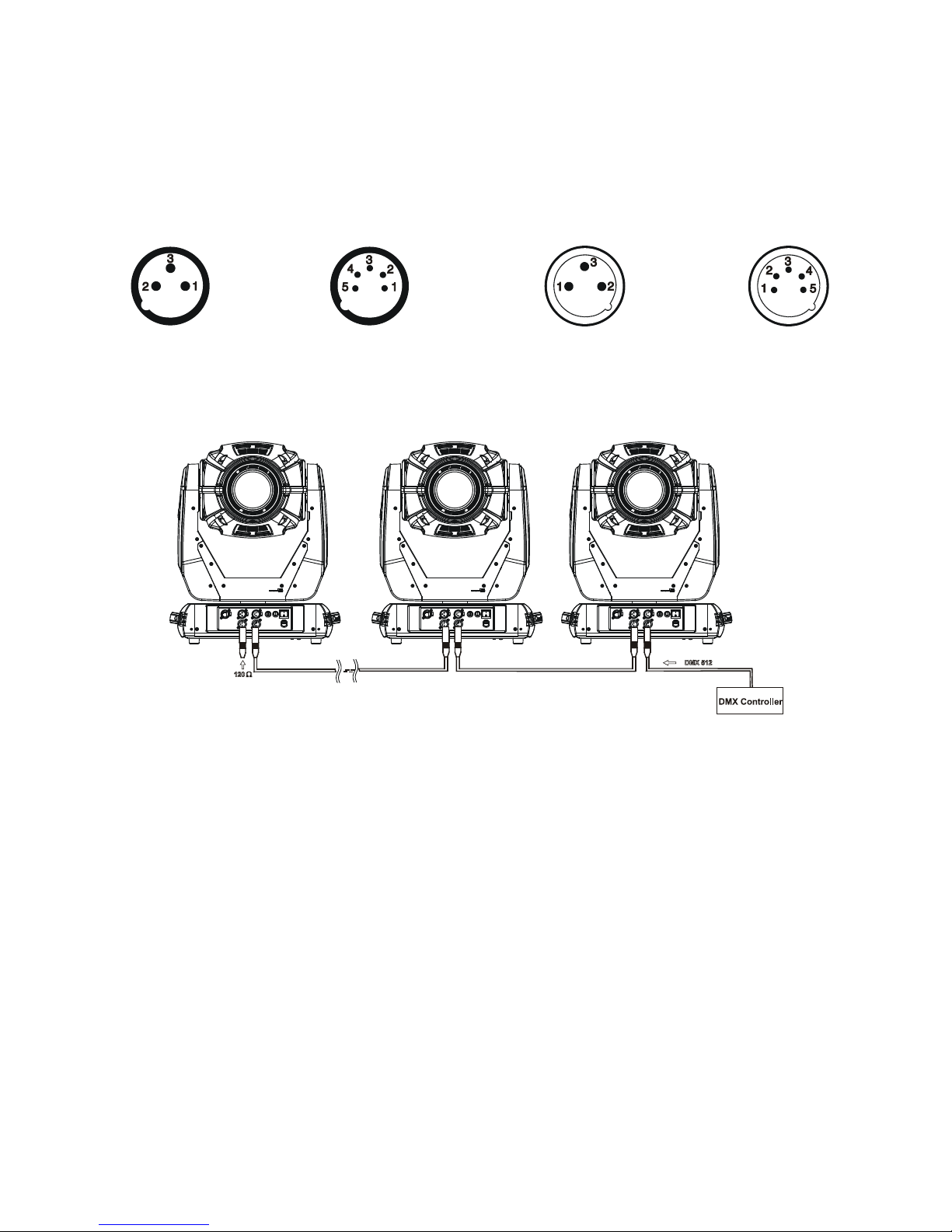
The xture is equipped with both 3-pin and 5-pin XLR sockets for DMX input and output.The sockets are wired
in parallel.
Only use a shielded twisted-pair cable designed for RS-485 and 3-pin or 5-pin XLR-plugs and connectors in
order to connect the controller with the xture or one xture with another.
DMX - output DMX-input
XLR mounting-sockets (rear view): XLR mounting-plugs (rear view):
If you are using the standard DMX controllers, you can connect the DMX output of the controller directly with
the DMX input of the rst xture in the DMX-chain. If you wish to connect DMX-controllers with other XLR-out-
puts, you need to use adapter-cables.
Building a serial DMX-chain:
Connect the DMX-output of the rst xture in the DMX-chain with the DMX-input of the next xture. Always
connect one output with the input of the next xture until all xtures are connected.
Caution: At the last xture, the DMX-cable has to be terminated with a terminator. Solder a 120 Ω resistor
between Signal (–) and Signal (+) into a 3-pin XLR-plug and plug it in the DMX-output of the last xture.
1 - Shield
2 - Signal (-)
3 - Signal (+)
4 - Not connected
5 - Not connected
1 - Shield
2 - Signal (-)
3 - Signal (+)
4 - Not connected
5 - Not connected
Dieses Handbuch passt für folgende Modelle
1
Inhaltsverzeichnis
Beliebte Beleuchtungsausrüstung Handbücher anderer Marken


Qazqa
Qazqa Suplux SL 3 Black 103062 Bedienungsanleitung

Commercial Electric
Commercial Electric 54568141 Bedienungsanleitung

CREE LIGHTING
CREE LIGHTING 304 Series Bedienungsanleitung

Goobay
Goobay 49867 Bedienungsanleitung

ECOMAN ITALIA
ECOMAN ITALIA LED T8 Bedienungsanleitung

Alkalite
Alkalite Krypton KT-81 Bedienungsanleitung


