Vegas D5063 Bedienungsanleitung

Vegas D5063 Service Manual
1
SERVICE MANUAL
15"LCD Monitor
D5063
THESE DOCUMENTS ARE FOR REPAIR SERVICE INFORMATION ONLY. EVERY REASONABLE
EFFORT HAS BEEN MADE TO ENSURE THE ACCURACY OF THIS MANUAL; WE CANNOT
GUARANTEE THE ACCURACY OF THIS INFORMATION AFTER THE DATE OF PUBLICATION AND
DISCLAIMS RE LIABILITY FOR CHANGES, ERRORS OR OMISSIONS.
P/N : 41A50-169

Vegas D5063 Service Manual
2
I. Revision List
Revision Date Change Description
A00 2002.01.18 Initial Version
A01 2002.01.23 Draft Version
A02 2002.02.06 1.) Add 4.1 Input Signal Connector
2.) Add 4.3 Power Supply Requirements
3.) Add 4.4 Panel Specification
4.) Add 5.1 Monitor Exploded View
5.) Improve 6.2 Inverter/Power Board Schematic Quality
6.) Improve 7.2, 7.3, 7.4 Layout Quality
7.) Add 8. Maintainability
A03 2002.03.05 Approved Version
A04 2002.07.28 1.) Add HSD Panel Part
2.) Update Part Lists

Vegas D5063 Service Manual
3
II. Table of Contents
I. Revision List ............................................................................................................................. 2
II. Table of Contents .................................................................................................................... 3
1. MONITOR SPECIFICATIONS ............................................................................................ 5
2. LCD MONITOR DESCRIPTION......................................................................................... 6
3. OPERATING INSTRUCTIONS............................................................................................ 7
3.1 GENERAL INSTRUCTIONS ............................................................................................................... 7
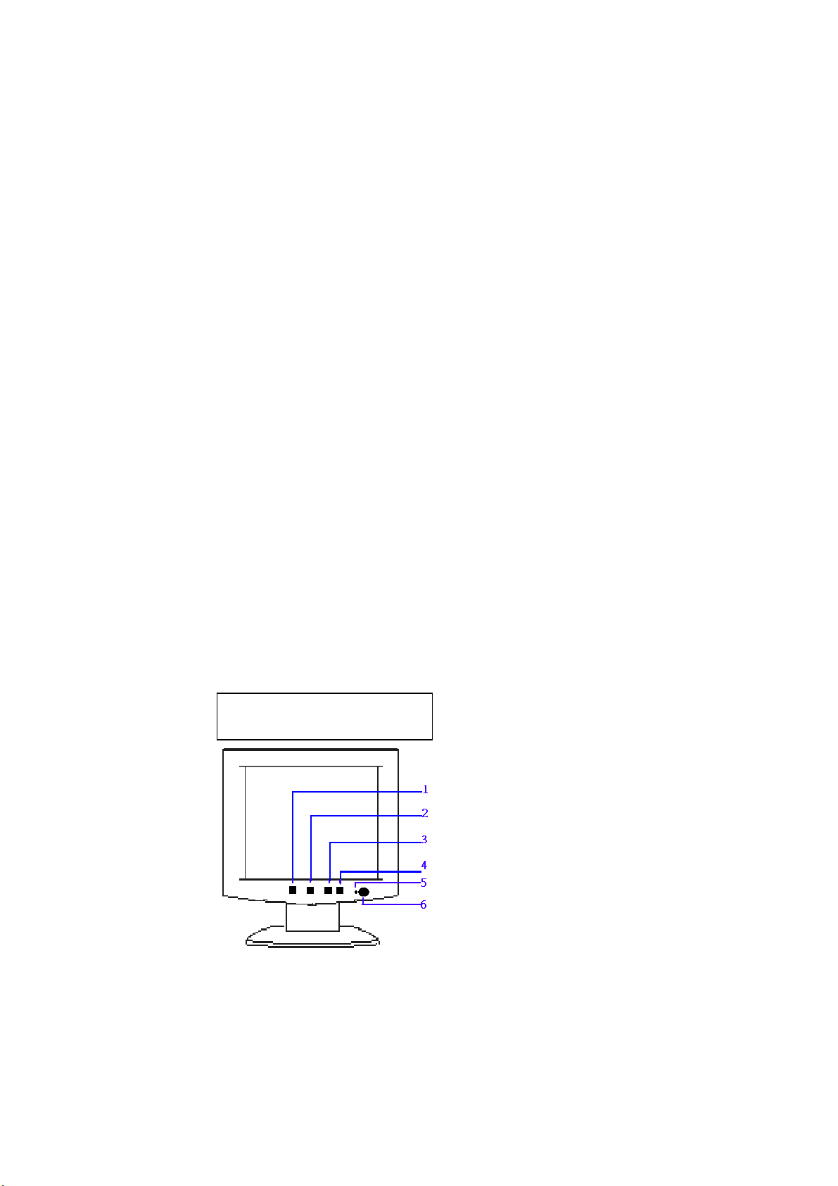
3.2 CONTROL BUTTONS .......................................................................................................................... 7
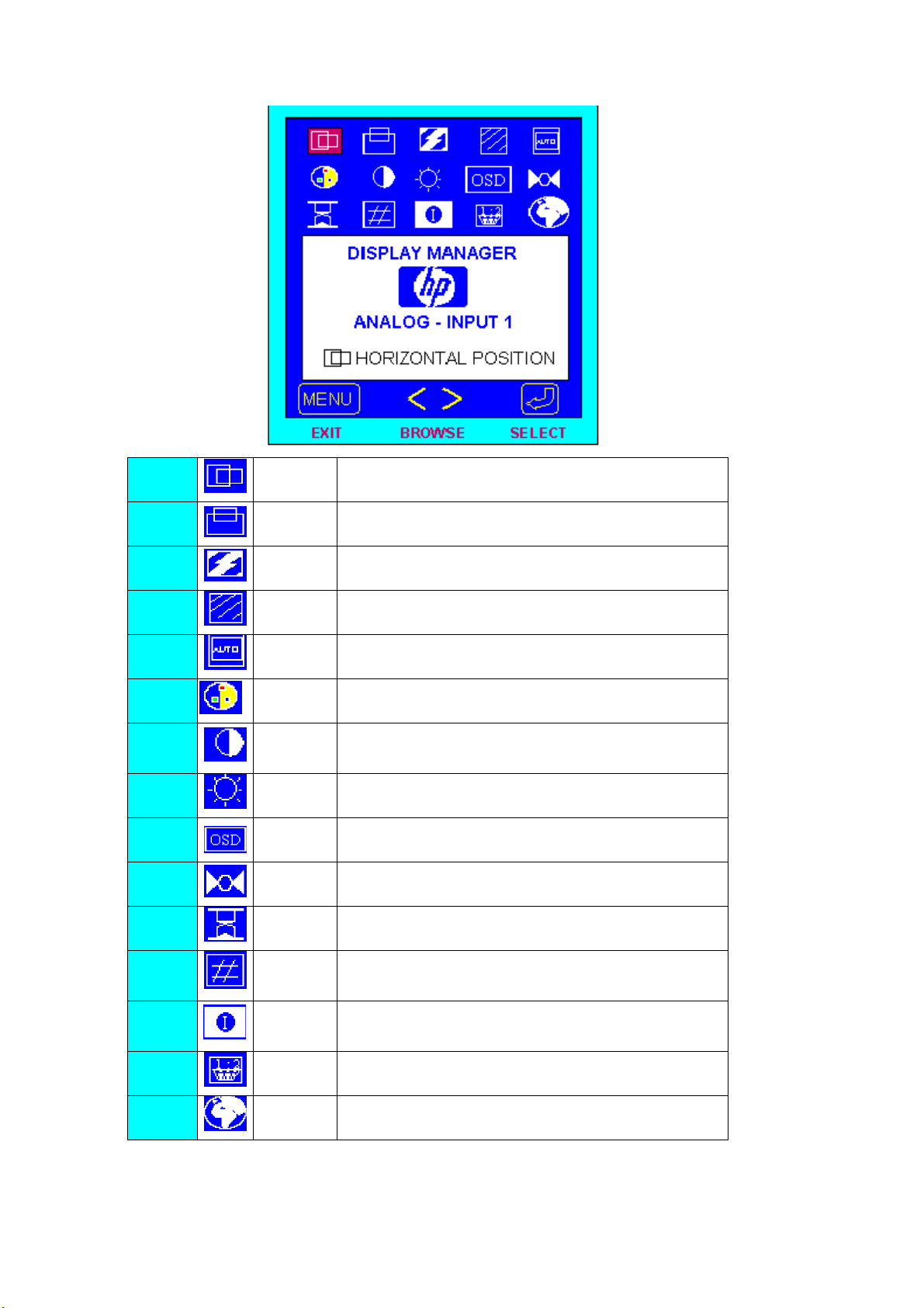
3.3 ADJUSTING THE PICTURE ............................................................................................................... 8
4. Input/Outpt Specification ....................................................................................................... 9
4.1 Input Signal Connector.......................................................................................................................... 9
4.1.1 Analog D-SUB Connector............................................................................................................. 9
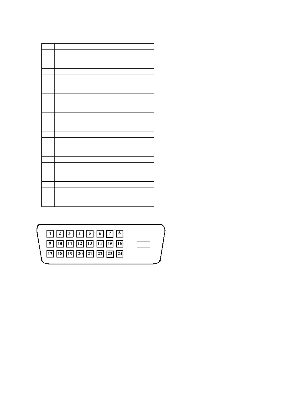
4.1.2 DVI-D Connector ........................................................................................................................ 10
4.2 Preset Mode Timing ..............................................................................................................................11
4.3 Power Supply Requirements ............................................................................................................... 12
4.3.1 Input Requirements ..................................................................................................................... 12
4.3.2 Output Requirements................................................................................................................... 12
4.3.3 Compatible Power Adaptors List................................................................................................. 12
4.4 PANEL SPECIFICATION (AU L150X3M-1/-2-7 & HSD150MX41-C) ......................................... 13
4.4.1 Panel Feature ............................................................................................................................... 13
4.4.2 Display Characteristics................................................................................................................ 13
4.4.3 Optical Characteristics................................................................................................................. 13
4.4.4 Parameter guide line for CCFL Inverter...................................................................................... 14
5. Block Diagram ....................................................................................................................... 15
5.1 Monitor Exploded View ....................................................................................................................... 15
5.1.1 D5063M....................................................................................................................................... 15
5.1.2 D5063A ....................................................................................................................................... 17
5.2 Software Flow Chart ............................................................................................................................ 19
5.3 Electrical Block Diagram..................................................................................................................... 21
5.3.1 Main Board.................................................................................................................................. 21
5.3.2 Inverter/Power Board .................................................................................................................. 22
5.3.3 Audio Board (D5063M) .............................................................................................................. 23
6. Schematic................................................................................................................................ 24
6.1 Main Board ........................................................................................................................................... 24
6.2 Inverter/Power Board .......................................................................................................................... 29
6.3 KeyPad Board....................................................................................................................................... 31
6.4 Audio Board(D5063M)......................................................................................................................... 32
7. PCB Layout ............................................................................................................................ 33
7.1 Main Board ........................................................................................................................................... 33
7.2 Inverter/Power Board .......................................................................................................................... 36
7.3 Keypad Board ....................................................................................................................................... 39

Vegas D5063 Service Manual
4
7.4 Audio Board(D5063M)......................................................................................................................... 40
8. Maintainability....................................................................................................................... 41
8.1 Equirements and Tools Requirement ................................................................................................. 41
8.2 Trouble Shooting................................................................................................................................... 42
8.2.1 Main Board.................................................................................................................................. 42
8.2.2 Power/Inverter Board .................................................................................................................. 43
8.2.3 KeyPad Board.............................................................................................................................. 46
8.2.4 Audio Board (D5063M) .............................................................................................................. 47
8.3 Alignment Procedure............................................................................................................................ 48
8.4 DDC Writing ......................................................................................................................................... 49
8.4.1 DDC Writing Procedure .............................................................................................................. 49
8.4.2 EDID Content.............................................................................................................................. 49
8.4.3 Serial Number Format ................................................................................................................. 50
9. Part Lists ................................................................................................................................ 51

Vegas D5063 Service Manual
5
1. MONITOR SPECIFICATIONS
Driving system TFT Color LCD
LCD Panel Size 38.1cm(15.0")
Pixel pitch 0.297mm( H )x 0.297mm( V )
Viewable angle 120˚(H) 100˚(V)
Response time (typ.) 30 ms
Video Analog / DVI-D
Input Sync. Type H/V TTL Separate and Composite Sync.
H-Frequency 30kHz – 60kHz
V-Frequency 56-75Hz
Display Colors 16.7 million Colors
Dot Clock 80MHz
Max. Resolution 1024 x 768
Plug & Play VESA DDC2BTM
Power Consumption ON Mode
(D5063A)
<23W
ON Mode
(D5063M)
<30W
OFF Mode
(Audio Volume=0)
<3W
Maximum Screen Size Horizontal : 12.0”(304.128mm)
Vertical : 9.0”(228.096mm)
Power Source 90~264VAC,47~63Hz
Environmental
Considerations
Operating Temp: 10°C to 35°C
Storage Temp.: -10°C to 60°C
Operating Humidity : 20% to 80%
Weight (N. W.)
D5063A 4.2Kgs Unit (net)
D5063M 4.7Kgs Unit (net)

Vegas D5063 Service Manual
6
2. LCD MONITOR DESCRIPTION
The LCD MONITOR will contain an main board, an inverter/power board, keypad board and external adapter
which house the flat panel control logic, brightness control logic and DDC.
The Inverter board will drive the backlight of panel and the DC-DC conversion .
The Adapter will provides the 12V DC-power to inverter/power board .
Inverter Board
(
with DC-DC module
)
Flat Panel and
CCFL backlight
Main Board
Keyboard
RS232 Connector
For white balance
adjustment in
factory mode
ADAPTER
HOST Computer
CCFT Drive.
AC-IN
90V-264V Video signal, DDC
Monitor Block Diagram

Vegas D5063 Service Manual
7
3. OPERATING INSTRUCTIONS
3.1 GENERAL INSTRUCTIONS
Press the power button to turn the monitor on or off. The other control buttons are located at front panel of the monitor. By changing
these settings, the picture can be adjusted to your personal preferences.
-The power cord should be connected.
-Connect the video cable from the monitor to the video card.
-Press the power button to turn on the monitor, the power indicator will light up.
3.2 CONTROL BUTTONS
-Power Button:
When pressed, the monitor enters the off mode, and the LED turns blank. Press again to restore normal status.
-Left / Right Button:
The Left/Right Button is used to control the monitor functions. Press to switch functions or adjust settings.
-Auto Adjust Key:
The Auto Adjust Key is used to automatically set the H Potision, V Potision, Clock and Phase.
-Power Indicator:
Green — Power On mode.
Orange — Power Saving mode.
Blank — Power Off Mode.
AUDIO BASE CONTROL (D5063M ONLY ) :
-Volume
Adjustable Audio volume.
-Earphone-jack
-Micphone-jack
CONTROL Buttons
Menu
< / Brightness
> / Contrast
Auto/Select
LED indicator
Power Button

Vegas D5063 Service Manual
8
3.3 ADJUSTING THE PICTURE
1. H Position Adjust the horizontal position of the picture.
2. V Position Adjust the vertical position of the picture.
3. Phase Adjust picture Phase.
4. Clock Adjust picture Clock.
5. Auto Config Automatically set the H Potision, V Potision, Clock and Phase
6. Color Choose color temperature of 9300K / 6500K / 5800K / User
Color
7. Contrast Adjust the picture contrast.
8. Brightness Adjust the picture brightness.
9.
OSD
Manager
Adjust OSD function of Protected OSD(password : 040990),
OSD Timeout, Info On/Off, OSD H/V Position.
10. Mode Recall Restored H/V Position, Clock and Phase.
11. Backlight
info
Display the Backlight Elapsed Time.
12. Serial
Number
Display Serial Number.
13. Mode Info Preset and User Mode List.
14. Input Priority Select Signal Input Priority
15. Language Select Language

Vegas D5063 Service Manual
9
4. Input/Outpt Specification
4.1 Input Signal Connector
4.1.1 Analog D-SUB Connector
Video Cable Pinout
PIN SIGNAL
1 Red Video
2 Green Video
3 Blue Video
4 TXD (for factory alignment)
5 Return
6 Red GND
7 Green GND
8 Blue GND
9 +5V (for reading EDID file when monitor is turned off)
10 Sync GND
11 RXD (for factory alignment)
12 Bidirectional DDC Data (SDA)
13 Horizontal Sync
14 Vertical Sync
15 DDC Data Clock (SCL)
Video Cable Connector Pins
PIN 1
PIN 5
PIN 9
PIN 11

Vegas D5063 Service Manual
10
4.1.2 DVI-D Connector
DVI-D Connector to be compliant to the latest DVI-DDWG specification version available.
Video Cable Pinout
PIN SIGNAL
1 TMDS RX2-
2 TMDS RX2+
3 TMDS RX2 GND
4 NC
5 NC
6 DDC Data Clock (SCL)
7 Bidirectional DDC Data (SDA)
8 NC
9 TMDS RX1-
10 TMDS RX1+
11 TMDS RX1 GND
12 NC
13 NC
14 +5V
15 GND
16 Hot Plug Detect
17 TMDS RX0-
18 TMDS RX0+
19 TMDS RX0 GND
20 NC
21 NC
22 TMDS RXC GND
23 TMDS RXC+
24 TMDS RXC-
C5 NC
Video Cable Connector Pins
C5
Inhaltsverzeichnis


