VLT 670 Series Montageanleitung

Installation, Operating &
Maintenance Instructions
966914EA Edition 2019-02-01
Symmetrical flow control & isolation valve
Series 670
DN 350 mm (I. D. 14"
)
This manual is valid for the following product ordering number
67051-JA52-ABY2

Series
670
2/40
Edition 2019-02-01 966914EA
Imprint
Manufacturer
VAT Vakuumventile AG, CH-9469 Haag, Switzerland
Website:
Phone:
Fax:
Email:
www.vatvalve.com
+41 81 771 61 61
+41 81 771 48 30
Publisher
VAT Vakuumventile AG, CH-9469 Haag, Switzerland
Editor
VAT Vakuumventile AG, CH-9469 Haag, Switzerland
Print
VAT Vakuumventile AG, CH
-
9469 Haag, Switzerland
Copyright
©
VAT Vakuumventile AG
2019
No part of these Instructions may be reproduced in any way (photocopies,
microfilms or any other reproduction processes) nor may it be manipulated with
electronic systems, duplicated or distributed without written permission from VAT.
Offenders are liable to pay damages.
The original VAT firmware and updated state of the art versions of the VAT
firmware are intended for use with VAT products. The VAT firmware contains a
limited, time unlimited user license. The VAT firmware may not be used for
purposes other than those intended nor is it permitted to make copies of the VAT
firmware. In particular, it is strictly forbidden to give copies of the VAT firmware to
other people.
The use of trade names, brand names, trademarks, etc. in these Instructions
does not entitle third parties to consider these names to be unprotected and to
use them freely. This is in accordance with the meaning of the laws and acts
covering brand names and trademarks.

Series 670
966914EA Edition 2019-02-01 3/
40
Contents
1
Description of product........................................................................4
1.1
Identification of product ...................................................................................................4
1.2
Use of product.................................................................................................................4
1.3
Used abbreviations..........................................................................................................4
1.4
Related documents..........................................................................................................4
1.5
Important information.......................................................................................................4
1.6
Technical data.................................................................................................................5
1.6.1
Valve unit...........................................................................................................5
2
Safety ...................................................................................................6
2.1
Compulsory reading material...........................................................................................6
2.2
Danger levels ..................................................................................................................6
2.3
Personnel qualifications...................................................................................................7
2.4
Safety labels....................................................................................................................7
3
Design and Function...........................................................................8
3.1
Design.............................................................................................................................8
3.2
Function...........................................................................................................................8
4
Installation...........................................................................................9
4.1
Unpacking .......................................................................................................................9
4.2
Installation into the system............................................................................................10
4.2.1
Installation space condition..............................................................................10
4.2.2
Installation overview.........................................................................................11
4.2.3
Installation procedure (mechanical, connection)..............................................12
4.2.4
Installation procedure (homing) .......................................................................13
4.3
Admissible forces..........................................................................................................14
5
Operation...........................................................................................15
6
Trouble shooting...............................................................................16
7
Maintenance ......................................................................................17
7.1
Maintenance intervals....................................................................................................18
7.2
Maintenance procedures...............................................................................................18
7.2.1
Removing the plate and plate seal replacement..............................................19
7.2.2
Remove the actuator and replace the bellows feedthrough.............................22
7.2.3
Mount the actuator...........................................................................................28
8
Repairs...............................................................................................31
9
Dismounting and Storage.................................................................32
9.1
Dismounting ..................................................................................................................32
9.2
Storage..........................................................................................................................33
10
Packaging and Transport.................................................................34
10.1
Packaging......................................................................................................................34
10.2
Transport.......................................................................................................................35
11
Disposal.............................................................................................36
12
Spare parts ........................................................................................37
13
Appendix............................................................................................39

DESCRIPTION OF PRODUCT Series
670
4/40
Edition 2019-02-01 966914EA
1 Description of product
1.1 Identification of product
The fabrication number and order fabrication are fixed on the product directly or by means of an
identification plate.
made in Switzerland
Fabrication No.:
670 . . - . . . . - . . . . / . . . .
A - . . . . . .
Fabrication number
Order
number
1.2 Use of product
Use product for clean and dry vacuum applications only. Other applications are only allowed with the
written permission of VAT.
1.3 Used abbreviations
Abbreviation Description
SFV Symmetrical flow valve
CPA Control performance analyser
1.4 Related documents
•
Product data sheet
•
Dimensional drawing
•
External controller manual (903522EA)
1.5 Important information
This symbol points to a very important statement that requires particular attention.
Example
:
VAT disclaims any liability for damages resulting from inappropriate packaging.

Series 670 DESCRIPTION OF PRODUCT
966914EA Edition 2019-02-01 5/
40
1.6 Technical data
1.6.1 Valve unit
Describtion
Symmetrical flow functional principle (given)
Pressure range at 20 °C 1 × 10E-8 mbar to 1.2 bar (abs)
Leak rate to outside at 20 °C 1 × 10E-8 mbar
l/s
Leak rate valve seat at 20 °C 1 × 10E-7 mbar
l/s
Max. differential pressure on plate at isolation 1200 mbar (from chamber side)
10 mbar (from pump side)
Max. differential pressure on plate during operation 30 mbar
Cycles until first service (under vacuum)
- Isolation cycles (open - closed - open)
- Throttling cycles (open - max. throttle - open)
200’000 (unheated and under clean conditions)
2’000’000 (unheated and under clean conditions)
Admissible operating temperature 10 °C to +120 °C
(dT body/plate max. 40K)
Ambiente temperature max. +50°C (35°C recommended)
Mounting position Horizontal (actuators downwards)
Process side
materials flange Aluminum EN AW-6082 T651 (3.3211)
plate Aluminum EN AW-6082 T651 (3.3211)
actuator shafts Stainless steel 316L (1.4435 or 1.4404)
bellows Stainless steel 633 (AM350)
bolts Stainless steel A4 (316)
Seals plate Kalrez
®
9500
actuator Kalrez
®
9500
Max. controllable conductance (N
2
molecular flow) 43´000 l/s (max. 130 mm stroke)
Min. controllable conductance (N
2
molecular flow) 0.35 l/s
Actuating time open to max. throttle (throttling only) typ. 1.0 s per 100 mm
max. throttle to open (throttling only)
typ. 1.0 s per 100 mm
isolation (max. trottle to isolation)
typ. 1.0 s
de-isolation (max. trottle to isolation)
typ. 1.0 s
Stroke mechanical maximum 130 mm
effective According to controller configuration, refer to product
data sheet of respective controller
Weight Approx. 35 kg
Dimensions Refer to dimensional drawing 898149

SAFETY Series
670
6/40
Edition 2019-02-01 966914EA
2 Safety
2.1 Compulsory reading material
Read this chapter prior to performing any work with or on the product. It contains important information
that is significant for your own personal safety. This chapter must have been read and understood by
all persons who perform any kind of work with or on the product during any stage of its serviceable
life.
NOTICE
Lack of knowledge
Failing to read this manual may result in property damage.
Firstly, read manual.
These Installation, Operating & Maintenance Instructions are an integral part of a
comprehensive documentation belonging to a complete technical system. They must
be stored together with the other documentation and accessible for anybody who is
authorized to work with the system at any time.
2.2 Danger levels
DANGER
High risk
Indicates a hazardous situation which, if not avoided, will result in death or serious
injury.
WARNING
Medium risk
Indicates a hazardous situation which, if not avoided, could result in death or serious
injury.
CAUTION
Low risk
Indicates a hazardous situation which, if not avoided, may result in minor or moderate
injury.
NOTICE
Command
Indicates a hazardous situation which, if not avoided, may result in property damage.
Series 670 SAFETY
966914EA Edition 2019-02-01 7/
40
2.3 Personnel qualifications
WARNING
Unqualified personnel
Inappropriate handling may cause serious injury or property damage.
Only qualified personnel are allowed to carry out the described work.
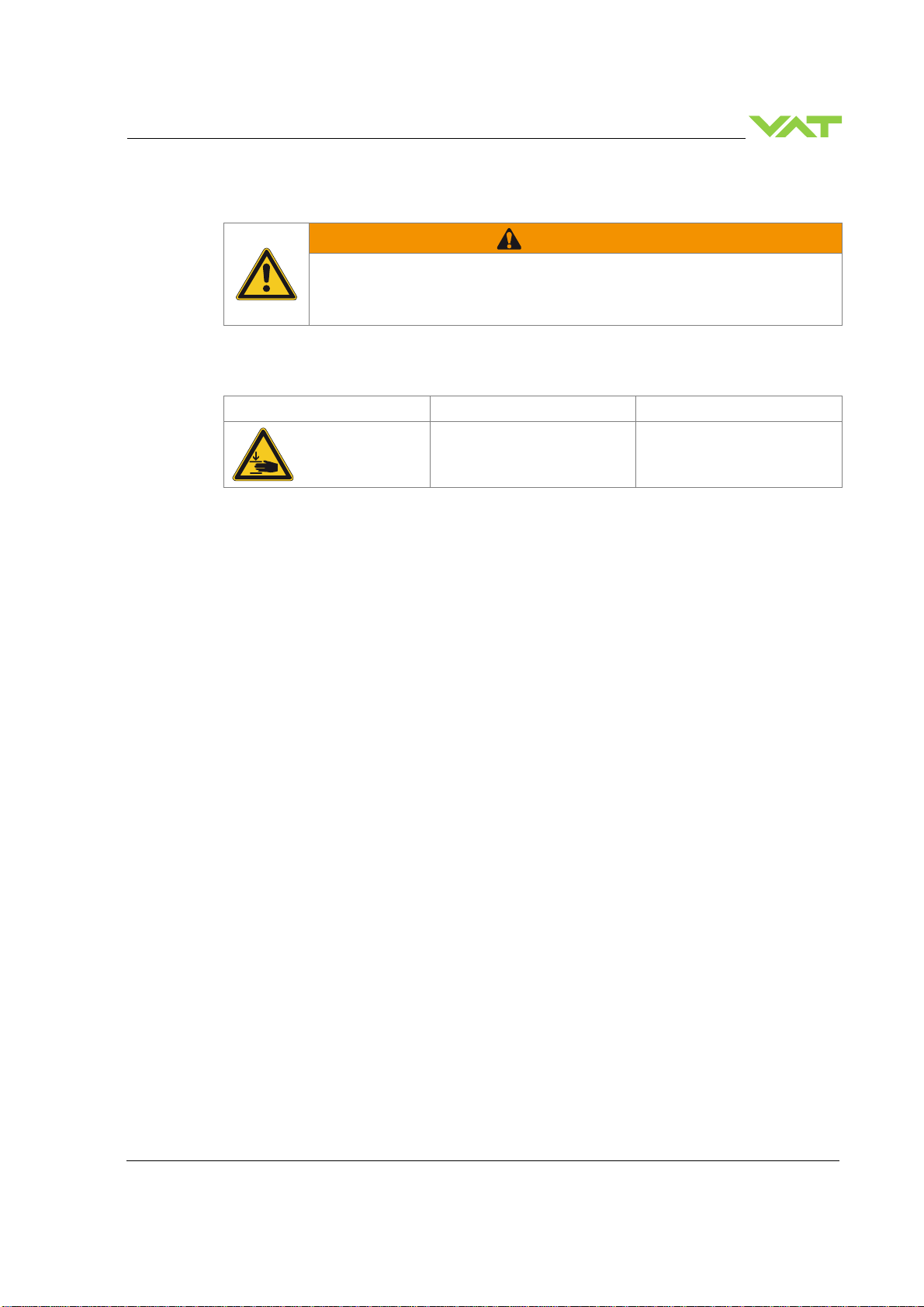
2.4 Safety labels
Label Part No. Location on valve
T-9001-156 On protective foil covering the
valve opening

DESIGN AND FUNCTION Series
670
8/40
Edition 2019-02-01 966914EA
3 Design and Function
3.1 Design
Sample pictutre
1 Flange seal (customer side) 6 Intermediate piece
2 Plate screw 7 Actuator shaft with bellows
3 Plate 8 Actuator (stepper motor)
4 Plate seal Valve seat side
5 Flange
3.2 Function
The valve plate (3) acts as a throttling element and varies the conductance of the valve opening. The
controller calculates the required plate position to achieve the set point pressure. Actuation is
performed by two synchronous stepper motors (8). Encoders monitor the position. This principle
ensures fast and accurate process pressure control.
6
2
3
4
1
5
8
7

Series 670 INSTALLATION
966914EA Edition 2019-02-01 9/
40
4 Installation
WARNING
Unqualified personnel
Inappropriate handling may cause serious injury or property damage.
Only qualified personnel are allowed to carry out the described work.
4.1 Unpacking
WARNING
Heavy weight
Physical overstraining.
Use a crane to lift valves DN 200 (8”) and larger.
NOTICE
Physical overstraining at actuators
Inappropriate handling with the valve may cause in damage of actuator.
Do not place the valve on the actuators.
•
Make sure that the supplied products are in accordance with your order.
•
Inspect the quality of the supplied products visually. If it does not meet your
requirements, please contact VAT immediately.
•
Store the original packaging material. It may be useful if products must be returned
to VAT.

INSTALLATION Series
670
10/40
Edition 2019-02-01 966914EA
4.2 Installation into the system
CAUTION
Valve opening
Risk of injury.
Do not connect the controller to power before the valve is installed complete into the
system.
NOTICE
Wrong connection
Wrong connection may result in damage of controller or power supply.
Connect all cables exactly as shown in the following schematic.
NOTICE
Burned connector pins (spark)
Connector pins or electronic parts could damage, if plugged and unplugged under
power.
Do not plug or unplug connectors under power.
NOTICE
Contamination
Gate and other parts of the valve must be protected against contamination.
Always wear clean room gloves when handling the valve.
•
Make sure that the sealing surfaces of the valve and the chamber are undamaged.
•
Mount valve to a clean system only.
4.2.1 Installation space condition
Install the valve with actuators with space for dismantling and air circulation as shown
in figure below. (sample picture)
Dieses Handbuch passt für folgende Modelle
1
Inhaltsverzeichnis
Beliebte Steuereinheit Handbücher anderer Marken

Festo
Festo Compact Performance CP-FB6-E Stücklistenhandbuch

Elo TouchSystems
Elo TouchSystems DMS-SA19P-EXTME Bedienungsanleitung

JS Automation
JS Automation MPC3034A Bedienungsanleitung

JAUDT
JAUDT SW GII 6406 Series Kurzanleitung

Spektrum
Spektrum Air Module System Bedienungsanleitung

BOC Edwards
BOC Edwards Q Series Bedienungsanleitung


