
Voltaire AT Series Bedienungsanleitung

AT VDC Series
Installation and
Maintenance Manual
VoltAire Systems, LLC
Specifications are subject to change without notice
Page 1 of 17
VoltAire Doc. # CA2919D
Published: December 9, 2020
INSTALLATION, OPERATION AND
MAINTENANCE MANUAL FOR AT SERIES
48VDC AIR CONDITIONING UNITS
Air Conditioners with Capacity of
4,000 through 12,000 BTU/HR Nominal
48 VDC Models
* A more recentrevision may be available at www.voltairesys.com or the QR Code in the top right corner of every page.

AT VDC Series
Installation and
Maintenance Manual
VoltAire Systems, LLC
Specifications are subject to change without notice
Page 2 of 17
VoltAire Doc. # CA2919D
Published: December 9, 2020
TABLE OF CONTENTS
1. Important Information to Review Prior to Installation, Operation and Maintenance.......................................Page 3
2. Parts Shipped Loose and Tools/Materials Provided by the Installer.............................................................Page 4
3. Product Description ......................................................................................................................................Page 5
4. General Product Data...................................................................................................................................Page 6
5. Installation Instructions .................................................................................................................................Page 9
6. Recommended / Preventative Maintenance...............................................................................................Page 13
7. Troubleshooting Guide................................................................................................................................Page 14
8. Spare Parts.................................................................................................................................................Page 16
9. Warranty.....................................................................................................................................................Page 16

AT VDC Series
Installation and
Maintenance Manual
VoltAire Systems, LLC
Specifications are subject to change without notice
Page 3 of 17
VoltAire Doc. # CA2919D
Published: December 9, 2020
1. IMPORTANT INFORMATION TO REVIEW PRIOR TO INSTALLATION,
OPERATION AND MAINTENANCE
READ THE ENTIRE MANUAL PRIOR TO INSTALLING AND MAINTAINING the VoltAire Systems Air
Conditioners. Do not install or perform maintenance on the air conditioner if you do not understand all of the
instructions. Contact VoltAire Systems at (407) 378-7482 with any questions or concerns.
The air conditioner should be fully inspected on initial delivery. Open the packaging completely at the time of
initial delivery and verify there is nohidden or concealed damage. Shipping damage, including concealed
damage, is not covered under warranty.
WARNING: IMPROPER INSTALLATION AND OPERATION MAY CAUSE PROPERTY DAMAGE,
PERSONAL INJURY OR LOSS OF LIFE. The air conditioner shall only be installed and serviced by a certified
professional in strict accordance with the requirements within this manual, in accordance with all
local/state/federal codes, and per industry standards. Remove power from the unit during maintenance and
installation, as line voltage may be dangerous, hazardous and lethal.
In the event of a conflict, code requirements shalltake precedence over the instructions provided within this
manual. The installer shall be aware of all code requirements and shall comply fully.
Use care when transporting and lifting the air conditioner. The unit should be maintained in the upright
position at all times. If the unit has been mistakenly laid on its side stand the unit up and wait at least 24 hours
before applying power.
WARNING: WEAR PROPER PERSONAL PROTECTION EQUIPMENT, INCLUDING BUT NOT LIMITED TO
SAFETY GLASSES, GOGGLES, AND GLOVES. EDGES MAY BE SHARP.
A field provided time delay fuse or breaker must be provided by the installer with the power supply circuit
serving the air conditioner. The installer shall size this fuse / breaker and wirein accordance with all applicable
codes. Verify wire terminals and voltage prior to plugging into the Air Conditioner, otherwise you may damage
the electrical components.
IMPORTANT NOTE: Valve service ports are provided with rubber gasketed caps that are used to fully seal the
service ports. If the caps are removed for service, they must be put back following service to prevent any
potential leakage through the valves.
These instructions should be retained by the owner and/or with the unit.
WARNING: This unit is to be supplied with 48VDC Voltage (+20%/-15%); The 48VDC board includes nominal
54V diodes for protection of voltage over 54V, up to approximately 57V. If the installer or user anticipates
voltage spikes in excess of 47V, VoltAire highly recommends that a voltage protection device be provided with
the 48VDC power supply to prevent unit failure, damage, and/or personal injury or loss of life.
WARNING: For Negative (-) 48VDC power supply carefully follow the instructions within this manual as unit
damage due to improper polarity is not covered under warranty. Do not rely upon wire color for polarity.

AT VDC Series
Installation and
Maintenance Manual
VoltAire Systems, LLC
Specifications are subject to change without notice
Page 4 of 17
VoltAire Doc. # CA2919D
Published: December 9, 2020
2. PARTS SHIPPED LOOSE AND TOOLS/MATERIALS PROVIDED BY THE
INSTALLER
Materials shipped loose in addition to this manual are as follows:
a) Mounting Gasket Field Kit
UNIT PART NUMBER
AT04RB/AT06RB B6F0004LAA
AT012RB B6F0092VAA
a) M6x25 Mounting Bolts
Unit Quantity
A
T04/AT06 10
A
T012RB 13
Required Tools and Materials provided by Installer:
a. Fuse and/or breaker
b. Exterior rated silicone sealant
c. Phillips head screw driver
d. T25 Security Torx (Allen head screw driver for AS models)
e. 4mm HEX head screw driver
f. Torque wrench
g. Personal Protection Equipment
h. Wire-Stripper

AT VDC Series
Installation and
Maintenance Manual
VoltAire Systems, LLC
Specifications are subject to change without notice
Page 5 of 17
VoltAire Doc. # CA2919D
Published: December 9, 2020
3. PRODUCT DESCRIPTION
VoltAire Systems AT Series Air Conditioning Units are designed for high efficiency and high performance heat
management of electronic enclosures or equipment. This product is an active thermal management system with an
internal refrigerant system and is designed for electronic environments. These products are designed to function
according to the data label found on the units.
Figure 1 shows the side of the AC unit and its intake and exhaust points for both the interior and exterior airflow path.
Exterior air enters the unit at the bottom-front and discharges air through the condenser coil at the top-front of the unit.
The interior air enters through the top-back of the unit and discharges conditioned air through the evaporator coil on the
bottom-back of the unit. As an additional option, airflow on the interior/evaporator side can be actively heated with an
electric element heater.
The unit is controlled with a control board that provides an easy to use interface to operate a Test Mode for startup and
diagnosis, configure operating parameters for temperature and alarm set points, provide anti-short cycling, monitor
operating pressure(s), provide visual alarms and diagnosis, and provides a HVAC trouble/temperature alarm dry contact
output.
Figure 1 – Airflow

AT VDC Series
Installation and
Maintenance Manual
VoltAire Systems, LLC
Specifications are subject to change without notice
Page 6 of 17
VoltAire Doc. # CA2919D
Published: December 9, 2020
4. GENERAL PRODUCT DATA
Figure 2 – Model Nomenclature
MODEL NUMBER NOMINAL SIZE
W x H x D (in.) WEIGHT
(lbs.)
NOMINAL
CAPACITY1
(BTU/HR
SENSIBLE)
RATED
VOLTAGE
EXTERNAL
OVER
CURRENT
PROTECTION
Minimum Supply
Voltage Wire
Gauge
AT04RB 17.1 x 29.6 x 12.9 78.5 4,000
48 VDC
+20% / -15%
16.4 AWG - 10
AT06RB 78.5 6,000 20.4 AWG - 10
A
T12RB 19.3 x 47.0 x 12.2 110.0
12,000
45.0
A
WG -
8
1 Capacity is nominal based upon free airflow without restrictions; Locating the air conditioner where airflow is restricted may reduce capacity;
Nominal capacity is at exterior temperature of 131ºF (55ºC) and interior temperature of 131ºF (55ºC)
Table 1 – AT (Telecom) Series General Product Specifications

AT VDC Series
Installation and
Maintenance Manual
VoltAire Systems, LLC
Specifications are subject to change without notice
Page 7 of 17
VoltAire Doc. # CA2919D
Published: December 9, 2020
Figure 3 – AT04RB / AT06RB Configuration
Figure 4 – AT12RB Configuration

AT VDC Series
Installation and
Maintenance Manual
VoltAire Systems, LLC
Specifications are subject to change without notice
Page 8 of 17
VoltAire Doc. # CA2919D
Published: December 9, 2020
Figure 5 – AT04RB / AT06RB Dimensions
Figure 6 – AT12RB Dimensions

AT VDC Series
Installation and
Maintenance Manual
VoltAire Systems, LLC
Specifications are subject to change without notice
Page 9 of 17
VoltAire Doc. # CA2919D
Published: December 9, 2020
5. INSTALLATION INSTRUCTIONS
WARNING: REVIEW THIS MANUAL COMPLETELY PRIOR TO BEGINNING INSTALLATION, OR SERVICE.
FAILURE TO DO SO MAY RESULT IN IMPROPER OPERATION, UNIT DAMAGE, AND/OR PERSONAL/BODILY
HARM.
The unit may be installed on any flat vertical surface. Do not install the unit in a horizontal position and verify the unit
is level. The unit should be located on a cabinet or equipment such that airflow is not restricted by obstructions of the
interior or exterior airflow path, as obstruction of airflow willreduce capacity of the unit and may cause unit failure.
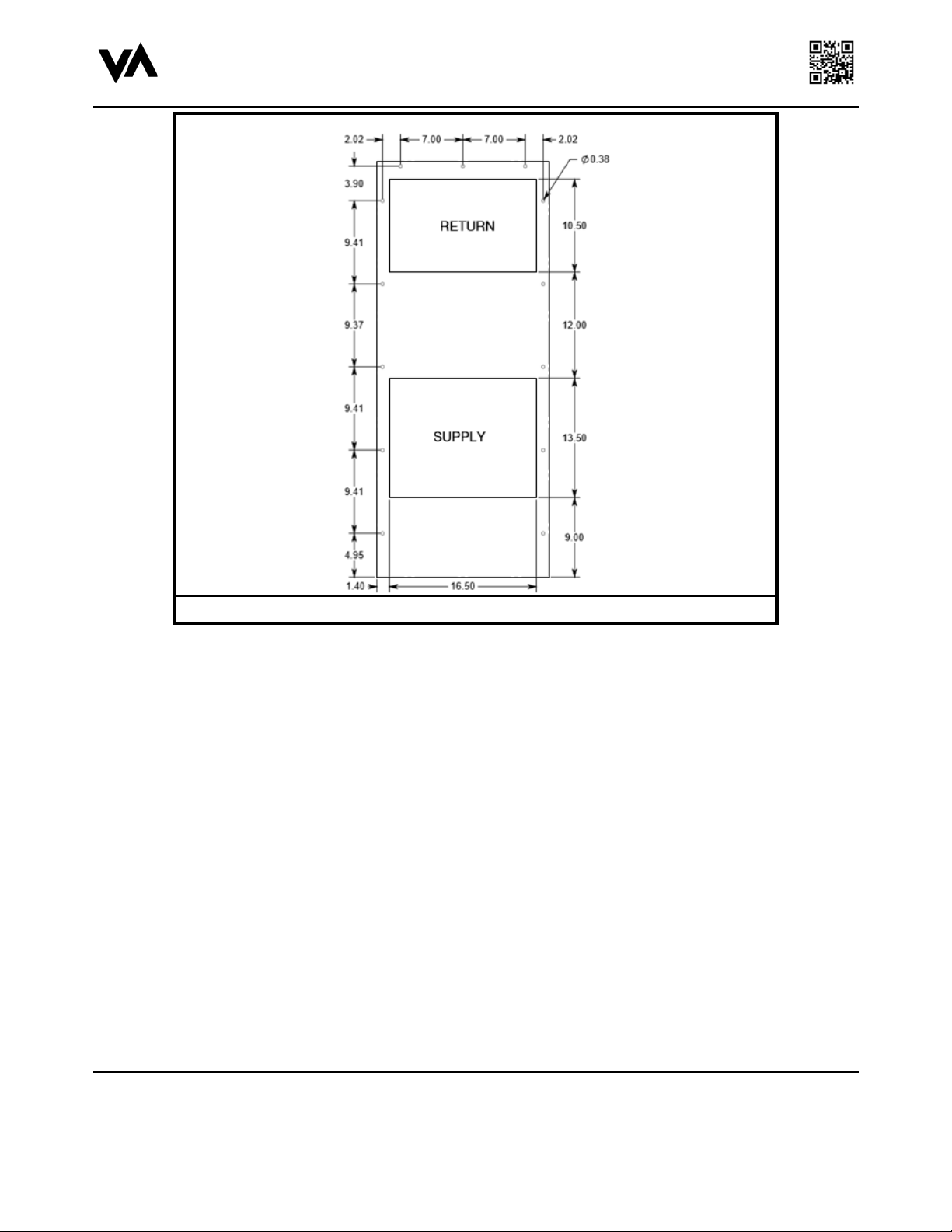
Prepare the wall for the interior intake and discharge openings and fastener locations using the cutout template that
matches your unit shown in Figures 7 and 8. Clean the mounting surface to remove any dust,grease, and/or debris,
including removing any metal burrs resulting from metal cutting.
Figure 7 – AT04RB / AT06RB Cutout
AT VDC Series
Installation and
Maintenance Manual
VoltAire Systems, LLC
Specifications are subject to change without notice
Page 10 of 17
VoltAire Doc. # CA2919D
Published: December 9, 2020
Figure 8 – AT12RB Cutout
A typical example of the gasket application is shown in Figure 9. The supplied gasket is compressed between the
cabinet and the air conditioning unit to prevent external water from entering the cabinet through the supply and return
openings as seen in Figures 7 and 8. Clean any dust ordebris from the designated gasket area shown in Figure 10
to ensure that the gasket properly adheres to the unit. Using theprovided gasket kit, place the gasket on the back of
the AC Unit immediately abutting the mountinghole locations. The gasket should run across the width of the top of
the unit, down bothsides, with two cross pieces underneath the mounting hooks and the evaporator coil. Be sure to
utilize the longer of the two shorter lengths for the top of the unit. This will maximize protection against water. Ensure
there are no gaps in the gasket and verify the top has no gap to ensure proper protection of rain or water.
Dieses Handbuch passt für folgende Modelle
3
Inhaltsverzeichnis


