Wasp WPD220VF Bedienungsanleitung

WPD-220 VF Pole Display
User’s Manual

© Copyright Wasp Technologies®2002.
All rights reserved.
Version 1.0
No part of this publication may be reproduced or transmitted in any form or by
any means without the written permission of Wasp Technologies®.The
information contained in this document is subject to change without notice.
Wasp is a trademark of Wasp Technologies®.All other trademarks or registered
trademarks are the property of their respective owners.

Table of Contents
Introduction ..........................................................................................................1
General Specifications..........................................................................................2
Interface Specifications ........................................................................................3
System Command Details ................................................................................4-6
Command........................................................................................................7-20
Character Set ....................................................................................................21
Dimensions ........................................................................................................23
Installation Guide................................................................................................24

1
WPD-220 VF User’s Manual
Introduction
INTRODUCTION
Thank you for choosing the WPD-220VF Pole Display. The WPD-220VF
provides both reliability and performance in a professional looking design.In this
guide, you will find connection and configuration information to help you connect
the display to your computer.
The WPD-220VF pole display uses a vacuum fluorescent display (VFD) tube
presenting bright and easy to read characters. Because of the VFD technology
the display is viewable from a wide angle. Users will appreciate not having to
remain in a fixed viewing position to see the display; they will be free to move
forward in line and still keep the display readable.The WPD-220VF pole display
has 2 pole sections giving you the choice of 4 different display heights. The
display can be rotated up to 270°.The head of the display can be tilted up to
35°.The combination of these features gives you flexibility to tailor the display
position to your unique application.
The WPD-220VF pole display uses an easy to connect RS-232C serial port
connection with a wide range of available communication speeds from 300 to
38,400bps.

SPECIFICATIONS
ITEM WPD-220VF
Display method Vacuum fluorescent display
Display color Blue green
Number of characters 40 characters(20 columns x 2 lines)
Brightness 700 cd/m2
Character type 96 alphanumeric
13 kinds of international character set
and 1 user-defined set
Character font 5 x 7dot matrix
Character size 3.5mm x 5.0mm
Character pitch 2mm
Power supply 5VDC or 12VDC or 24VDC
Power consumption 5W
MTBF(power on time) 25000hours
Dimensions 170(W) x 70(H) x 45(D)mm
Viewing angle ± 30 degrees
Rotation angle Maximum 270 degrees
Weight 0.9Kg
Environmental Operating Temperature 5-45°C
Conditions Humidity Less then 95%
Storage Temperature -5-55°C
Humidity Less then 95%
Safety FCC class B CE
2
WPD-220 VF User’s Manual
Specifications
Serial port (RS232C)
Serial port (RS232C) communication
(a) This interface specification is based on EIA RS232C baud rate 300 to 38400
BPS, 8 data bits, none parity, 1 or more stop bits
(b) Serial port (RS232C) communication data link
Data link flow chart:
PC/HOST displaydisplay printer printer PC/HOST
Control for RTS and DTR :
PC/HOST displaydisplay printer printer PC/HOST
(c) The device will activate DTR or RTS signal to PC/host in the following two
conditions:
1. Printer will activate DTR or RTS signal.
2.The pass through buffer is full ( 200 bytes ) .
* If PC/host keeps transmitting the data to printer when CD3220 activate
DTR or RTS, the data will be lost.
Serial port interface to the space-saving base portion
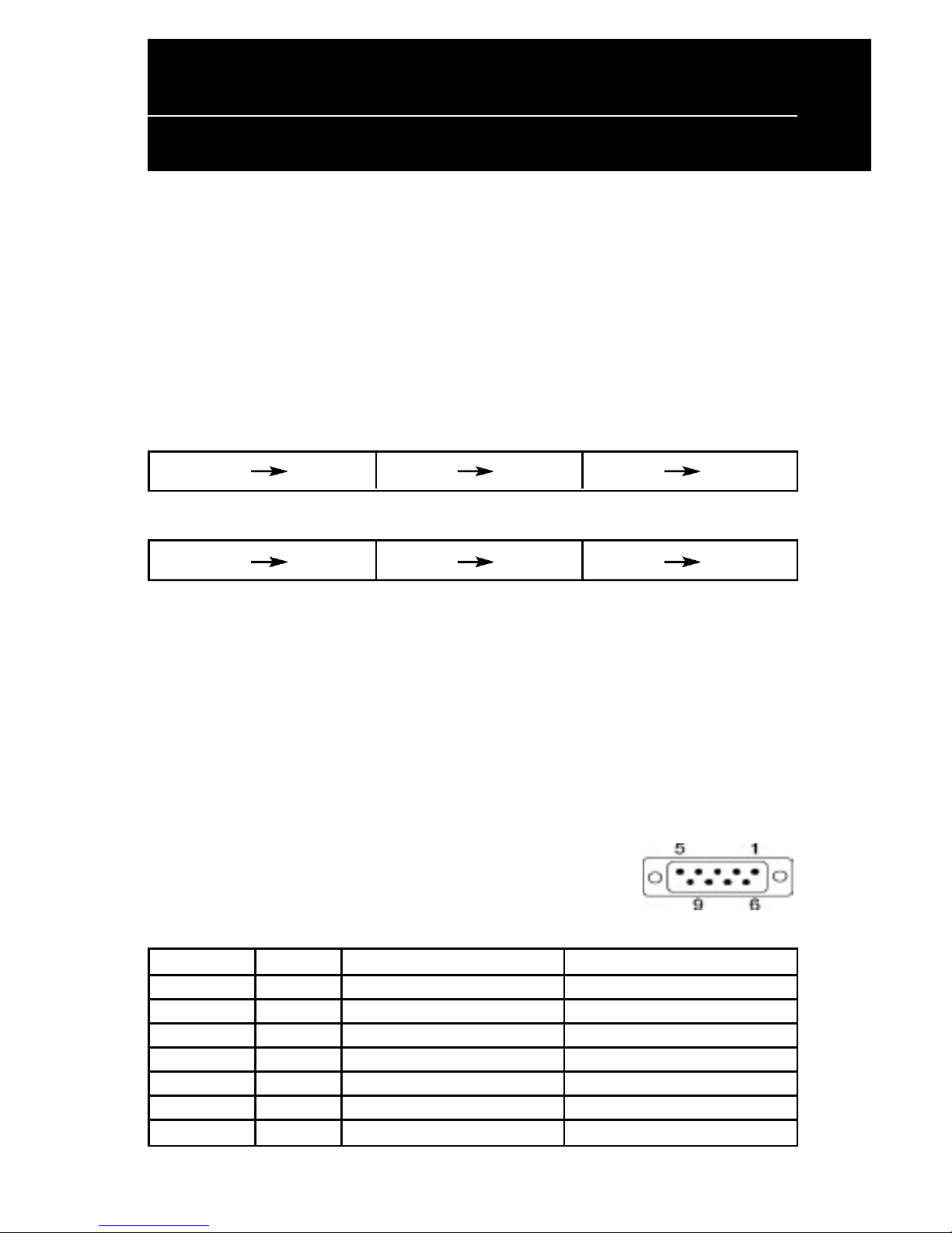
(c) RS232C interface to PC/HOST cable, PC/HOST side
connector pin assignment
Connector type: D-sub 9 pin (Male)
Pin No. Signal Direction Function description
2 TXD From printer to PC/Host Printer status data
3 RXD Input Receive data
4 DSR From PC/HOST to printer Host ready signal
5 GND Signal ground
6 DTR Output Display/printer ready signal
7 RTS Output Display/printer ready signal
8 CTS From PC/HOST to printer Host ready signal
3
WPD-220 VF User’s Manual
Interface Specifications

4
WPD-220 VF User’s Manual
System Command Details
Baud rate
STX 05 B n ETX /Set baud rate and keep it with EEPROM/
ASCII Format STX 05 B n ETX
Dec. Format [02][05][66] n [03]
Hex.Format [02h][05h] [42h] n [03h] 30h<n<37h
Description Change the display communication baud rate.The
baud rate setting can be selected from 300 to 38400.
The setting function will be saved to EEPROM.
N Baud rate
30h 9600
31h 4800
32h 2400
33h 1200
34h 600
35h 300
36h 38400
37h 19200
Reset EEPROM
STX 05 07 n ETX Reset EEPROM
ASCII Format STX 05 07 n ETX
Dec. Format [02][05][07][n][03]
Hex. Format [02h][05h][07h][n][03h]
Description This command will reset the content of EEPROM
(eg. demo scroll data, user-define character, baud
rate setting.)
n=31h clear all EEPROM contents
n=32h clear upper line data message
n=33h clear lower line data message

5
Loading the Ribbon
WPD-220 VF User’s Manual
System Command Details
Save data for demo display
STX 05 L n m ETX Save demo message to EEPROM
ASCII Format STX 05 L n m ETX
Dec. Format [02][05][76] n m [03]
Hex. Format [02h][05h][4Ch] n m [03h]
Description Save demo message for upper line and bottom line
n = 31h save data message for upper line
n = 32h save data message for lower line
m = data message; the maximum data
character is under 200
Run Demo message
STX 05 D 08 ETX Run demo message
ASCII Format STX 05 D 08 ETX
Dec. Format [02][05][68][08][03]
Hex. Format [02h][05h][44h][08][03h]
Description Run demo message for the display

6
WPD-220 VF User’s Manual
System Command Details
Set Communication Option
STX 05 P n ETX Set the communication parity
ASCII Format STX 05 P n ETX
Dec. Format [02][05][80] n [03]
Hex. Format 02h][05h][50h] n [03h] 31h<n<36h
Description Change the display communication parity.
Set 7 or 8 data bit and the parity set for
even, odd, or non-parity.
n Parity
31h N-8-1
32h N-7-1
33h E-8-1
34h E-7-1
35h O-8-1
36h O-7-1

7
WPD-220 VF User’s Manual
Command
Command List
STANDARD MODE
Command Code description (hex) Function description
ESC DC1 1B 11 overwrite mode
ESC DC2 1B 12 vertical scroll mode
ESC DC3 1B 13 horizontal scroll mode
ESC Q A ..........CR 1B 51 41 [n ]x20 0D set the string display mode, write string to
upper line
ESC Q B ..........CR 1B 51 42 [n ]x20 0D set the string display mode, write string to
lower line
ESC Q D ..........CR 1B 51 44 [n ]x20 0D upper line message scroll continuously
ESC [ D 1B 5B 44 move cursor left
BS 08 move cursor left
ESC [ C 1B 5B 43 move cursor right
HT 09 move cursor right
ESC [ A 1B 5B 41 move cursor up
ESC [ B 1B 5B 42 move cursor down
LF 0A move cursor down
ESC [ H 1B 5B 48 move cursor to home position
HOM 0B move cursor to home position
ESC [ L 1B 5B 4C move cursor to left-most position
CR 0D move cursor to left-most position
ESC [ R 1B 5B 52 move cursor to right-most position
ESC [ K 1B 5B 4B move cursor to bottom position
ESC [ x y 1B 6C x y move cursor to specified position
1≤x≤20,y=1,2
ESC @ 1B 40 initialize display
ESC W s x1 x2 y 1B 57 1 x1 x2 y reset window range at horizontal scroll mode
1≤x1≤x2≤20 y=1,2
Inhaltsverzeichnis


