Wayne HS Bedienungsanleitung
WAYNE COMBUSTION SYSTEMS
801 GLASGOW AVE.
FORT WAYNE, IN 46803
PHONE: ( 60) 4 5-9 00
(800) 443-46 5
FAX: ( 60) 4 4-0904 HSOil
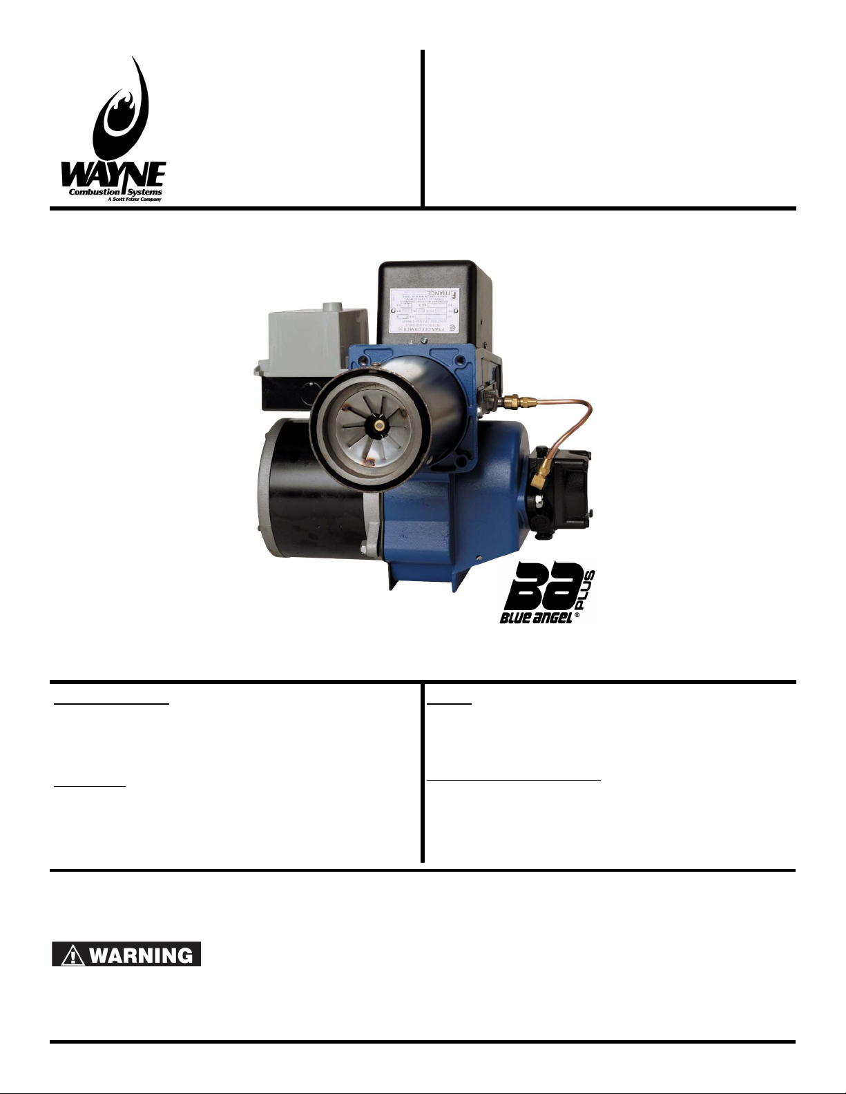
Burner
Manual: 1663
Revision 15
Publication Date: 7/ 6/ 011
Firing Capacity:
70,000 – 4 0,000 BTU/HR
0.50 – 3.00 GPH
(additional hardware required to fire above .50 GPH)
Electrical:
Power Supply..............115V / 60Hz / 1-Phase
Motor...............................................3450 RPM
Ignition...................................10,000V / 3mA
Fuels:
No.1 or No. heating oil, diesel, B5, kerosene,
or JP8 Jet Fuel
Dimensions (Standard):
Height.....................................................1 ½”
Width......................................................1 ⅞”
Depth........................................................7 ¾”
Center Line of Tube to Floor.........................7”
INSTALLATION OF BURNER
INSTALLATION OF THE BURNER MUST BE DONE BY A QUALIFIED INSTALLER IN ACCORDANCE WITH REGULATIONS OF THE NATIONAL
FIRE PROTECTION STANDARD FOR OIL-BURNING EQUIPMENT, NFPA NO. 1, AND IN COMPLETE ACCORDANCE WITH ALL LOCAL CODES
AND AUTHORITIES HAVING JURISDICTION.
INCORRECT INSTALLATION, ADJUSTMENT, OR MISUSE OF THIS BURNER COULD RESULT IN DEATH, SEVERE
PERSONAL INJURY, OR SUBSTANTIAL PROPERTY DAMAGE AND WILL VOID THE WARRANTY.
A QUALIFIED INSTALLER IS THE PERSON WHO IS RESPONSIBLE FOR THE INSTALLATION AND ADJUSTMENT OF THE EQUIPMENT AND
WHO IS LICENSED TO INSTALL OIL-BURNING EQUIPMENT IN ACCORDANCE WITH ALL CODES AND ORDINANCES.
THESE INSTRUCTIONS SHOULD BE AFFIXED TO THE BURNER
OR ADJACENT TO THE HEATING APPLIANCE.

Burner / Appliance Service Log
Service Date Contractor License # Actions Performed
/ /
/ /
/ /
/ /
/ /
/ /
/ /
/ /
/ /
/ /
/ /
/ /
/ /
/ /
/ /
/ /
/ /
/ /
/ /
/ /
/ /
/ /
/ /
/ /
/ /
/ /
/ /
/ /
/ /
/ /
/ /
/ /

Table of Contents
GENERAL INFORMATION
TO THE HOMEOWNER................................................................................................................................................... 1
HAZARD DEFINITIONS................................................................................................................................................... 1
GENERAL SPECIFCATIONS........................................................................................................................................... 1
APPROVALS.................................................................................................................................................................... 1
PREPARE INSTALLATION SITE
GENERAL INFORMATION...............................................................................................................................................
COMBUSTION CHAMBER..............................................................................................................................................
FUEL PUMPS................................................................................................................................................................... 3
FUEL LINES..................................................................................................................................................................... 3
FUEL TANKS.................................................................................................................................................................... 3
AIR SUPPLY FOR COMBUSTION................................................................................................................................... 3
CHIMNEY......................................................................................................................................................................... 3
DRAFT REGULATORS.................................................................................................................................................... 3
PREPARE BURNER
GUN ASSEMBLY REMOVAL........................................................................................................................................... 4
NOZZLE INSTALLATION................................................................................................................................................. 4
CHECK AND ADJUST ELECTRODE SETTINGS............................................................................................................ 4
GUN ASSEMBLY INSTALLATION.................................................................................................................................... 5
CALIBRATE AIR CONE POSITION.................................................................................................................................. 6
WIRING............................................................................................................................................................................ 6
STARTING PROCEDURE
STARTING BURNER........................................................................................................................................................ 7
FINAL ADJUSTMENTS.................................................................................................................................................... 7
SETTING COMBUSTION EFFICIENCY.......................................................................................................................... 8
FINAL CHECKS............................................................................................................................................................... 8
BURNER MAINTENANCE
SCHEDULED MAINTENANCE........................................................................................................................................ 9
BLOWER WHEEL REPLACEMENT................................................................................................................................. 9
SUNTEC PUMP INSTALLATION INFORMATION............................................................................................................ 9
NOZZLE SELECTION.................................................................................................................................................... 1
OIL PRIMARY SPECIFICATIONS.................................................................................................................................. 13
BURNER REPLACEMENT PARTS – MODEL HS......................................................................................................... 16
WAYNE® FUEL BLEND................................................................................................................................................. 17
MISCELLANEOUS
LIMITED WARRANTY.................................................................................................................................................... 18
NOTES........................................................................................................................................................................... 19

GENERAL INFORMATION
TO THE HOMEOWNER
Since 19 8, Wayne has supplied the Homeowners of the
world with high quality oil burners. You are obtaining a
superior burner unsurpassed in engineering design and
product development. If properly installed and serviced, it
will provide you with many years of efficient, trouble-free
operation. Please read this manual carefully.
Wayne warrants its burner specifically to those who have
purchased it for resale, including your dealer. If, in any
case, you have a problem with your burner, or its
installation, you should contact your dealer for assistance.
Wayne recommends yearly inspection/service of your oil
heating system by a qualified service agency or individual.
A qualified service agency or individual must be:
•Licensed or certified to install and provide technical
service to oil heating systems.
•Experienced with all applicable codes, standards and
ordinances.
•Responsible for the correct installation and commission
of the equipment.
•Skilled in the adjustment of oil burners using combustion
test instruments.
ELECTRIC SHOCK HAZARD
High voltages are present in
this equipment. Follow these rules to avoid electrical
shock:
- Use only a properly grounded circuit. A ground
fault interrupter is recommended.
- Do not spray water directly on burner.
- Turn off power before servicing.
- Read owner's manual before using
OVERHEATING HAZARD
Should overheating occur:
1. Shut off the manual oil valve to the appliance.
2. Do NOT shut off the control switch to the pump or
blower.
NEVER ATTEMPT TO USE
GASOLINE AS A FUEL FOR
THIS BURNER, AS IT IS MORE COMBUSTIBLE AND
COULD RESULT IN A SERIOUS EXPLOSION.
Incorrect installation,
adjustment or use of the
burner could result in severe personal injury death or
substantial property damage from fire, carbon
monoxide poisoning, soot or explosion.
Do not store or use gasoline or
other flammable vapors and
liquids in the vicinity of this or any other appliance.
HAZARD DEFINITIONS
Indicates an imminently hazardous
situation, which, if not avoided, will
result in death, serious injury, or property damage.
Indicates a potentially hazardous
situation, which, if not avoided,
could result in death, severe personal injury, or substantial
property damage.
Indicates a potentially hazardous
situation, which, if not avoided,
may result in personal injury or property damage.
Intended to bring special attention
to information, but not related to
personal injury or property damage.
GENERAL SPECIFCATIONS
Firing Rate: 0.50 – 3.00 GPH*
70,000 – 4 0,000 BTU/HR
Fuels:
No. 1 or No. heating oil, diesel, B5,
kerosene, or JP8 Jet Fuel ONLY
-NEVER burn garbage or refuse in the unit
-NEVER try to ignite oil by tossing burning
material into the heating unit
-NEVER burn waste or crankcase oil
Electrical:
Power Supply
115V / 60Hz / 1PH
Motor
3450 RPM, N.E.M.A. Flange, Auto Overload
Protection
Ignitior
10,000V / 3mA secondary, Continuous
Duty-Shielded Interrupted
Fuel Pump: Suntec
Mounting: Rigid Flange, Adjustable Flange, or Base
Mount
Dimensions:
Height..................................................1 ½”
Width...................................................1 ⅞”
Depth.....................................................7 ¾”
Center Line of tube to Floor.......................7”
* To fire over .50 GPH, additional hardware is required.
See “Burner Replacement Parts” for details
APPROVALS
This burner complies with ANSI/UL Standard 96 and is for
use with, No. 1 fuel oil, No. fuel oil, or B5 blend. State
and local approvals are shown on burner rating label. All
burners should be installed in accordance with the National
Fire Protection Association, and in complete accordance
with all local codes and authorities having jurisdiction.
Regulation of these authorities takes precedence over the
general instructions provided in this manual.
1

PREPARE INSTALLATION SITE
GENERAL INFORMATION
When installing the appliance and/or burner, be sure to
provide adequate space for easy service and maintenance.
Prior to installation of the oil burner, the heating system
should be carefully inspected for defects and cleanliness.
The flue passages and heat absorbing surfaces must be
clean to ensure maximum heat transfer. Soot acts as an
insulator, which retards the transfer of heat.
The combustion chamber, flue gas passages, and all doors
and openings must be tightly sealed to eliminate air
infiltration. Excess air decreases CO levels and thus
lowers efficiency. Inspect the flue and chimney for leaks
and obstructions.
Be sure the chimney is of adequate size and height. Install
a draft regulator the same size as the flue pipe (see page 3
under Chimneys and Draft Regulators).
Figure 1: Overall Burner Dimensions
COMBUSTION CHAMBER
The purpose of a combustion chamber is to maintain a high
flame temperature by reflecting the heat back into the flame.
A high temperature ensures greater combustion efficiency
and lower stack losses. An insulating refractory or a Fiber
Fax type chamber can be used with this burner.
Caution should be taken when
installing Flamelock™ burners in
stainless steel combustion chambers, because of the higher
temperature levels produced by high performance flame
retention burners. The temperature may exceed the
temperature ratings of the stainless steel chamber and can
result in chamber burnouts.
It is important to select and install, if necessary, the correct
size chamber on a conversion job. (Suggested chamber
dimensions are shown in Table 1.) On the Flamelock™
conversion burners, the atomized oil burns just off the
Flamelock™ cone. On all oil burners, the atomized oil must
not touch the sides or bottom of chamber, or smoke will
result (see Figure 1, page 13). Install the burner so the
face of the air cone of burner is set 1/4” behind the inside
face of the chamber (See Figure ).
To eliminate the smoke, excess air will be required, resulting
in high stack temperature and lower combustion efficiency.
When you are replacing a standard burner with a flame
retention burner, take the following precautions:
1. Use pliable ceramic liner to line the inside of chamber.
. Adjust burner (see “Final Adjustments” on page 7).
Table 1: Suggested Combustion Chamber
Dimensions
Conversion or Upgrading
Chamber Dimensions (in inches)
Firing
Rate
(GPH)
Square
Chamber
Diameter
Round
Chamber
Height Nozzle to
Floor
0.50 7 x 7 8 11 5 – 6
0.75 8 x 8 9 1 5 – 6
0.85 8½ x 8½ 9 1 5 – 6
1.00 9 x 9 10⅛ 1 ½ 5 – 6
1. 5 10 x 10 11¼ 1 ½ 5 – 6
1.35 10½ x 10½ 11¾ 1 ¾ 5 – 6
1.50 11 x 11 1 ⅜ 13 5 – 6
1.65 11½ x 11½ 13 13¾ 5 – 6
.00 1 ⅝ x 1 ⅝ 14¼ 13¾ 6 – 7
.50 14¼ x 14¼ 16 14 7 – 8
3.00 15½ x 15½ 17½ 15 7 – 8
The “Air Tube Length” is the distance from the front of the
aluminum fan housing to the face of the Air Cone.
The maximum insertion depth of
any given air tube is reduced by
the thickness of the adjustable flange. Example: A 6” air
tube can only be inserted about 5”.
Figure 2: Combustion Chamber Detail

FUEL PUMPS
The Model HS oil burner is provided with single stage 3450
RPM fuel pump for a single pipe installation. This is
satisfactory where the fuel supply is on the same level, or
above burner, permitting gravity flow of oil.
Never exceed PSI to the
suction side of the fuel pump.
A pressure over PSI may cause damage to the shaft
seal and allow it to leak oil.
When it is necessary to lift the oil to the burner, a return line
should be run between fuel pump and oil supply. (If lift
exceeds a height of 10 feet, a two-stage fuel pump must be
used with a return line.) When a two-line installation is
made, a bypass plug must be installed on the Suntec pump.
This is supplied with the burner, attached to the fuel pump,
along with a pump information data sheet in a plastic bag.
FUEL LINES
When oil lines are continuous runs, heavy wall copper
tubing is recommended. Avoid running oil lines overhead,
against the appliance, or across ceiling or floor joists; if
possible, install under the floor. Specific information on
piping, connections, lift capabilities and tank installations is
provided in the instruction sheet of the fuel pump
manufacturer.
Be sure that all connections are completely airtight. Check
all connections and joints. Flared fittings are recommended.
Do not use compression fittings. Avoid using fittings in
inaccessible locations.
Install shutoff valve in oil supply line in accessible locations,
one close to the tank, another close to the oil burner but
ahead of the filter.
Use an oil filter of adequate size on all installations. Install
the filter inside the building between the tank shutoff valve
and the burner.
If the maximum burner firing rate
exceeds the integral fuel pump
strainer rating, an external U/L listed filter/strainer must be
placed in the fuel line between the fuel tank and burner fuel
pump.
FUEL TANKS
Local codes and regulations must be followed regarding
tank and burner installation. Check existing tanks for water
and sludge accumulation, clean if necessary. Also clean or
replace existing piping.
AIR SUPPLY FOR COMBUSTION
A burner shall not be installed in an area where facilities for
normal air circulation or infiltration are so limited as to
interfere with ready obtainment of all air necessary for
proper combustion and venting.
When the heating appliance is installed in a confined space,
two permanent openings shall be provided: one near the top
of the enclosure and one near the bottom. Each opening
shall have a free area of not less than one square inch per
1000 BTU per hour (140 square inches per GPH) of the
total input rating of all the appliances in the enclosure.
If the house is of unusually tight construction, has a kitchen
ventilating system, exhaust fans, clothes dryer or vented
fireplaces, it is recommended that combustion air be
supplied through two permanent openings. The openings
shall communicate directly, or by means of ducts, with the
outdoors or to such spaces (attic or craw) that freely
communicate with outdoors. For additional information,
refer to ANSI standard NFPA 31.
CHIMNEY
Follow the recommendations of the appliance manufacturer.
A chimney shall be capable of producing a draft as required
by the appliance and as recommended by the appliance
manufacturer. It must be properly designed, of adequate
size, and should be above the surrounding objects, tile-
lined, with no obstructions, and be in good state of repair.
The smoke pipe should set flush with the inside of tile and
be cemented in place. All cleanout doors should be sealed.
A draft inducer may be used to overcome inadequate draft
conditions. If a draft inducer is used, provisions must be
made to insure the burner does not operate if the draft
inducer fails.
DRAFT REGULATORS
A draft regulator shall be provided unless otherwise
specified by the appliance manufacturer. The draft
regulator shall be installed in accordance with local codes
and regulations or in the absence of local codes, with the
American National Standard NFPA31. Refer to appliance
manufacturer’s instructions for recommended over-fire and
stack draft.
3

PREPARE BURNER
GUN ASSEMBLY REMOVAL
1. Remove the two cover plate screws holding the top
cover in place and swing the transformer/cover open.
. Disconnect the oil line fitting.
3. Remove the adjustment screw securing the gun
assembly in the burner. DO NOT loosen or remove
the screw securing the stop bracket in position.
4. Gently lift up and pull back on the gun; do not force it.
It may be necessary to rotate the gun assembly 90° to
help with it’s removal.
NOZZLE INSTALLATION
To install a nozzle:
1. Remove the gun assembly and loosen the clamping
screw (See Figure 4) on the flame retention assembly
and slide the assembly off the adapter.
. Inspect adapter face. Replace if nicked or scratched.
3. Install and tighten the nozzle in the adapter.
Do not touch the nozzle face or
hold the nozzle by its integral filter
as spray characteristics and flow may be affected. Be
careful not to damage the electrode insulators or bend the
electrodes.
4. Replace the flame retention assembly on the nozzle
adapter. Make sure the clamp is tight against the
shoulder on the adapter, and tighten the clamping
screw.
5. Check the electrode setting.
For information on selecting the
proper nozzle, see “Nozzle
Selection” on page 1 .
CHECK AND ADJUST ELECTRODE SETTINGS
The electrodes must be precisely spaced from the face of
the nozzle as shown in the following figure:
Figure 4: Nozzle/Electrode Settings
1. To check the height of the electrodes and the distance
from the nozzle face the electrode tips, place the
gauge in the end of the burner nozzle as shown in
Figure 5.
In this orientation, the point at
which the ruled scale on the
side of the gauge (P/N: 14200-002) crosses the edge of
the air cone corresponds to the Flamelock™ setting.
4
Figure : Gun Assembly Removal

Figure 5: HS Gauge, Position 1
. To check the spacing between the electrode tips,
rotate the gauge 90° and place the gauge against the
burner nozzle as shown in Figure 6.
Figure 6: HS Gauge, Position 2
3. To adjust the spacing of the electrodes, slightly loosen
the electrode clamping screw and move the
electrodes to their correct position.
GUN ASSEMBLY INSTALLATION
1. Slide the assembly into the air tube; do not force it.
The gun assembly must be lifted and guided through
the air cone at the end of the tube. Start with the end
of the oil pipe at the 1 o’clock position, slide the gun
forward until the Flamelock™ is located in the air
cone, then rotate it counterclockwise and position the
side cover between the guide rails.
. Pull the side bracket firmly back against the stop
bracket.
3. Reinstall and tighten the adjustment screw.
4. Reconnect the oil line fitting.
5. Close the transformer/cover so that the springs
contact the buss bars (Figure 7) and secure with the
two mounting screws.
Figure 7: Transformer Springs
Contacting Buss Bar
Care should be taken when
closing the transformer not to
pinch the lead wires between the housing and cover
plate.
5

CALIBRATE AIR CONE POSITION
If any components have been replaced on a given gun
assembly, it may be necessary to calibrate the air cone
position. As long as the stop bracket is not loosened or
removed, this procedure is not necessary during normal
maintenance.
1. Loosen the stop bracket, pull it back to the zero
position, and re-tighten the bracket as indicated in
Figure 8.
Figure 8: Stop Bracket
. Loosen the gun adjustment screw, slide the gun
assembly back until it is flat against the stop bracket,
and re-tighten the adjustment screw.
3. At this point, the Flamelock™ cone should be flush
with the stepped face of the air cone (See Figure 13,
page 7). If it is not flush, loosen the 3 screws
securing the air cone in place.
Figure 9: Air Cone Mounting Screws
4. Adjust the air cone to be flush with the Flamelock™
cone and tighten the 3 air cone screws.
5. After completing this calibration, it will be necessary to
re-tune burner and check combustion.
WIRING
All wiring must comply with the National Electric Code and
local ordinances. Refer to diagram supplied with burner or
controls, making sure the burner and controls are wired
correctly and that the line switch is properly connected to a
0 amp fused service.
To use with line voltage
thermostat, jumper terminals T-T
and add thermostat as shown at (1) in series with limit
control.
Figure 10: Intermittent Ignition Wiring
Figure 11: Interrupted Ignition Wiring
6

STARTING PROCEDURE
STARTING BURNER
1. Be sure main switch is in “OFF” position, thermostat is
substantially above room temperature, the oil tank is
filled, all valves are open, and controls set for
operation.
. Adjust air supply on burner by loosening the screw on
the primary air damper, and open partially. (See
Figure 1 and Table for inputs and damper
adjustments).
Table 2: Listed Burner Settings
GPH INPUT
FLAMELOCK
SETTING
“A”
STATIC
BAFFLE
ANGLE “B”
PRIMARY AIR
DAMPER
“C”
0.50 – 0.75 0 – (*0”) 65° Set to optimal
CO and trace
smoke.
0.85 – 1.75 – (*1/8”) 30°
.00 – 3.00 8 – (*1/ ”) 30°
Burner is equipped with Air Cone to fire 0.50 to .50 GPH,
and baffle to fire 0.50 to 0.75 GPH. Use air cone 100531-
001 for inputs over .50 GPH, and 30° baffle (packed
w/manual) for inputs over 0.75 GPH.
Setting “A” - Flamelock™ settings are a direct reading in
1/16” steps. A number setting indicates the Flamelock™
is 1/8 inch ahead of the Air Cone “Flush Setting”. (See
Figure 13)
Figure 12: Burner Settings
Figure 1 : Flamelock Diagram
Note the direction of the air
cone when installing it in the
air tube. The beveled side of the inner diameter is
installed toward the burner.
3. Open the inspection door and turn on switch.
4. Prime pump according to the pump manufacturer’s
recommendations and check pressure. If safety
lockout occurs, reset after one or two minutes. Do not
run fuel pump dry for more than five minutes.
5. When fire is established make a temporary air
adjustment for a clean combustion flame, reduce air
supply until flame tips appear slightly smoky, then
readjust so flame tips are clean looking.
6. Leave inspection door open until chamber is dry.
7. When normal temperatures are reached, close
inspection door. (See page 3 under “Draft
Regulators”).
FINAL ADJUSTMENTS
1. At this point, a final adjustment should be made by the
use of a COMBUSTION TEST KIT.
. After operating ten minutes to warm up the unit, a
smoke tester should be used to take a smoke reading.
Smoke test should read no greater than #1 (Shell
Bacarach scale), and less than a #1 smoke is desired.
At times, a new heating unit requires more time than
this to burn clean due to the oil film on the new heater
unit surfaces.
7
Andere Handbücher für HS
1
Inhaltsverzeichnis
Andere Wayne Brenner Handbücher

Wayne
Wayne HSG200 Bedienungsanleitung

Wayne
Wayne stealth Bedienungsanleitung

Wayne
Wayne MSR-DC Bedienungsanleitung

Wayne
Wayne P265DI Bedienungsanleitung

Wayne
Wayne P250AF Bedienungsanleitung

Wayne
Wayne HS Bedienungsanleitung

Wayne
Wayne EHASR-DC Bedienungsanleitung

Wayne
Wayne EHA Bedienungsanleitung

Wayne
Wayne MSR Bedienungsanleitung

Wayne
Wayne EHG Bedienungsanleitung


