WITTUR USG-25P Bedienungsanleitung

Blatt/
sheet
D729MGB.000
Datum/
date
23.05.2007
Stand/
version
G-07.05.2018
Geprüft/
approved
WAT/MZE
Änderungen vorbehalten! Subject to change without notice!
Progressive Safety Gear
USG-25P
Operating Instructions
D729MGB 05.2018
*D729MGB$111*
Progressive Safety Gear
USG-25P
ID Unique PM.7.000342.EN
Original Instruction
Product manufacturer reference can be found on the product type label.
or any support or further questions please contact your trading office.
No part of this publication may be reproduced or translated, even in part, without prior written permission from WITTUR. We reserve the right to make alterations with respect to the specifications
and figures in this manual. Original operating instruction language is english.
www.wittur.com

Blatt/
sheet
D729MGB.001
Datum/
date
23.05.2007
Stand/
version
G-07.05.2018
Geprüft/
approved
WAT/MZE
Änderungen vorbehalten! Subject to change without notice!
Progressive Safety Gear
USG-25P
Operating Instructions
1 General information prior to installation
1.1 Description and functions . . . . . . . . . . . . . . . . . . . . . . . . . . . . . . . . . . . . . . . . . . . . . . . . . . . . . . . . . .002
1.2 Liability and guarantee . . . . . . . . . . . . . . . . . . . . . . . . . . . . . . . . . . . . . . . . . . . . . . . . . . . . . . . . . . . .003
1.3 Safety precautions . . . . . . . . . . . . . . . . . . . . . . . . . . . . . . . . . . . . . . . . . . . . . . . . . . . . . . . . . . . . . . . .003
1.4 Preparation . . . . . . . . . . . . . . . . . . . . . . . . . . . . . . . . . . . . . . . . . . . . . . . . . . . . . . . . . . . . . . . . . . . . . .004
1.5 Advice for when working on safety components . . . . . . . . . . . . . . . . . . . . . . . . . . . . . . . . . . . . . . .004
1.6 Content of supply . . . . . . . . . . . . . . . . . . . . . . . . . . . . . . . . . . . . . . . . . . . . . . . . . . . . . . . . . . . . . . . .005
2 Name plate, designation, identification
2.1 Labelling according to EN81 (CE) . . . . . . . . . . . . . . . . . . . . . . . . . . . . . . . . . . . . . . . . . . . . . . . . . . . .006
2.2 Labelling according to GOST R 53780 (Russia) . . . . . . . . . . . . . . . . . . . . . . . . . . . . . . . . . . . . . . . . .007
2.3 Range of use . . . . . . . . . . . . . . . . . . . . . . . . . . . . . . . . . . . . . . . . . . . . . . . . . . . . . . . . . . . . . . . . . . . . .008
3 Installation and adjustment
3.1 Mounting to the car frame . . . . . . . . . . . . . . . . . . . . . . . . . . . . . . . . . . . . . . . . . . . . . . . . . . . . . . . . .009
3.1.1 Mounting with lat bars (integrated solution) . . . . . . . . . . . . . . . . . . . . . . . . . . . . . . . . . . .010
3.2 Adjustment of running clearance (gap brake lining to guide rail) . . . . . . . . . . . . . . . . . . . . . . . . .011
3.3 Dimensioning and cut of synchronisation shaft (type A) . . . . . . . . . . . . . . . . . . . . . . . . . . . . . . . .012
3.4 Synchronisation of the safety gear (type A) . . . . . . . . . . . . . . . . . . . . . . . . . . . . . . . . . . . . . . . . . . .013
3.5 Assembling and adjustment of housing (type B) and synchronisation . . . . . . . . . . . . . . . . . . . . .014
3.6 Electrical installation of thesafety gear switch of housing (type B) . . . . . . . . . . . . . . . . . . . . . . .016
3.6.1 Safety gear switch . . . . . . . . . . . . . . . . . . . . . . . . . . . . . . . . . . . . . . . . . . . . . . . . . . . . . . . . . .016
4 Function testing
4.1 irst acceptance test . . . . . . . . . . . . . . . . . . . . . . . . . . . . . . . . . . . . . . . . . . . . . . . . . . . . . . . . . . . . . .017
4.2 Static functions test . . . . . . . . . . . . . . . . . . . . . . . . . . . . . . . . . . . . . . . . . . . . . . . . . . . . . . . . . . . . . . .018
4.3 Dynamic functions test . . . . . . . . . . . . . . . . . . . . . . . . . . . . . . . . . . . . . . . . . . . . . . . . . . . . . . . . . . . .019
4.3.1 Gripping test for car safety gear . . . . . . . . . . . . . . . . . . . . . . . . . . . . . . . . . . . . . . . . . . . . . . .019
4.3.2 Gripping test for counterweight safety gear . . . . . . . . . . . . . . . . . . . . . . . . . . . . . . . . . . . . .020
4.3.3 Checking safety gear, car and counterweight . . . . . . . . . . . . . . . . . . . . . . . . . . . . . . . . . . . .021
4.3.4 Visual checks after a safety gear test . . . . . . . . . . . . . . . . . . . . . . . . . . . . . . . . . . . . . . . . . . .021
4.4 Gripping distance . . . . . . . . . . . . . . . . . . . . . . . . . . . . . . . . . . . . . . . . . . . . . . . . . . . . . . . . . . . . . . . . .022
4.4.1 Determining the gripping distance . . . . . . . . . . . . . . . . . . . . . . . . . . . . . . . . . . . . . . . . . . . . .022
4.4.2 Checkingthe gripping distance . . . . . . . . . . . . . . . . . . . . . . . . . . . . . . . . . . . . . . . . . . . . . . . .022
5 Maintenance, inspection and repair
5.1 Maintenance and inspection . . . . . . . . . . . . . . . . . . . . . . . . . . . . . . . . . . . . . . . . . . . . . . . . . . . . . . . .024
5.1.1 General . . . . . . . . . . . . . . . . . . . . . . . . . . . . . . . . . . . . . . . . . . . . . . . . . . . . . . . . . . . . . . . . . .024
5.1.2 Maintenance and inspection check list . . . . . . . . . . . . . . . . . . . . . . . . . . . . . . . . . . . . . . . . .025
5.1.3 Cleaning of guide rails . . . . . . . . . . . . . . . . . . . . . . . . . . . . . . . . . . . . . . . . . . . . . . . . . . . . . . .025
5.2 Periodical tests . . . . . . . . . . . . . . . . . . . . . . . . . . . . . . . . . . . . . . . . . . . . . . . . . . . . . . . . . . . . . . . . . . .025
5.3 Operational life time of the safety gears . . . . . . . . . . . . . . . . . . . . . . . . . . . . . . . . . . . . . . . . . . . . . .026
5.4 Carrying out repairs . . . . . . . . . . . . . . . . . . . . . . . . . . . . . . . . . . . . . . . . . . . . . . . . . . . . . . . . . . . . . . .026
5.5 Spare parts list (type A) . . . . . . . . . . . . . . . . . . . . . . . . . . . . . . . . . . . . . . . . . . . . . . . . . . . . . . . . . . . .027
5.6 Spare parts list (type B) . . . . . . . . . . . . . . . . . . . . . . . . . . . . . . . . . . . . . . . . . . . . . . . . . . . . . . . . . . . .028
6 Revision Table
Contents Page

Blatt/
sheet
D729MGB.002
Datum/
date
23.05.2007
Stand/
version
C-07.09.2011
Geprüft/
approved
WAT/MZE
Änderungen vorbehalten! Subject to change without notice!
Progressive Safety Gear
USG-25P
Operating Instructions
1.1 Description and functions
The progressive type safety gear USG-25P is a
combined c-type spring, frame and friction ele-
ment, which is activated by a movable roller. The
braking force is adjusted by means of variable
machining dimensions, therefore the re-adjusting
is impossible. The safety gears are fixed normally
below the car or counterweight frame. There is
always a pair of safety gears used.
When the tripping speed of the overspeed gover-
nor is reached during downward drive, the safety
gear is engaged.
The overspeed governor rope is blocked and pulls
the lifting lever up into brake position. Both safe-
ty gears, connected by a gripping shaft will grip
at the same time.
The uniform braking of both safety gears is
caused by a good synchronisation during mount-
ing. This must be done very carefully.
The release of the safety gear is done by moving
the car or counterweight upward about 100mm.
With the exception of resetting the safety switch,
which must be done by trained personal (if the
safety gear is equipped with a manual resetable
switch), is the safety gear ready for operation im-
mediately.
If this safety component is handled with care and
scheduled examination is performed, it will be
very long live and fail save.
The operating range is defined as follows:
• max. elevator speed 2,0 m/s
• width of guide rail head 8 - 16 mm
• max. mass to be gripped max = 2600kg
• governor tripping force max. 1000N
1. Spring Body
2. Gripping Roller
3. Brake lining
4. Guide plate
5. Housing (optional)
6. Lifting lever
7. Reset spring
8. Reset limiter
1 2
3
4
58
7
6
1 General information prior to installation

Blatt/
sheet
D729MGB.003
Datum/
date
23.05.2007
Stand/
version
C-07.09.2011
Geprüft/
approved
WAT/MZE
Änderungen vorbehalten! Subject to change without notice!
Progressive Safety Gear
USG-25P
Operating Instructions
1.2 iability and guarantee
This instruction handbook is written for people
who are familiar with lift servicing and installa-
tion. Sufficient knowledge of lifts is essential.
WITTUR accept no responsibility for damage
caused by improper handling, or for damage
caused as a result of actions other than those
stated in these operating instructions.
The WITTUR guarantee may be voided if parts
other than those described in these instructions
are installed.
Unless stated otherwise, the following are not
permissible due to technical safety reasons:
• The use of components other than those in-
stalled
• Carrying out modifications, of any kind on
the safety gear
• Installing two different brake heads with dif-
ferent index numbers together
• Combining different component types
• Installing progressive safety gears intended
for other employment than that stipulated
• Carrying out faulty or improper maintenance
or inspection checks
• Using unsuitable accessories, spare parts or
operating material which has neither been
re-leased by the WITTUR Company nor con-
sists of original WITTUR spare parts
1.3 Safety precautions
WITTUR machine installation or repair engineers
are chiefly responsible for the safe operation of
machinery.
It is essential to comply with and keep abreast of
all safety rules and legal obligations in order to
avoid personal / product damage during installa-
tion, maintenance and repair work.
Important safety advice and danger warnings are
emphasised with the following symbols:
General danger warning
High danger risk warning (i.e. crushing
edge, cutting edge etc.).
Risk of damage to machinery parts (e.g.
due to incorrect installation, or such like).
Important information sign
These operating instructions belong with the
whole installation and must be kept in a safe
place at all times (i.e. machine room).
The proper assembly and installation of WITTUR
safety gears requires correspondingly well trained
fitting engineers. The responsibility of training
lies with the company appointed to carry out the
work.

Blatt/
sheet
D729MGB.004
Datum/
date
23.05.2007
Stand/
version
C-07.09.2011
Geprüft/
approved
WAT/MZE
Änderungen vorbehalten! Subject to change without notice!
Progressive Safety Gear
USG-25P
Operating Instructions
Before starting installation work:
Only properly trained personnel may carry
out work, or be allowed access to the in-
stallation site.
- Attach safety devices to guard against falling
(platform or harnesses)
- Cover any floor openings
- Secure installation tools or objects against
accidental falling
- Lift shaft openings should be cordoned off
and suitable warning signs should be erected
when working in shaft openings
- Work involving electrical equipment should
only be carried out by an electrical engineer
or qualified personnel.
1.4 Preparation
Before beginning installation work it is in your
own interest to ascertain the constructional and
spatial conditions. Where (workshop or on site)
and when which installation operations can or
must be carried out. It is recommended therefore,
taking into account all the given circumstances,
to plan the various operational sequences in ad-
vance, rather than carrying them out prematurely
and in an unconsidered manner.
On receipt of the delivery, the goods or compo-
nents should be checked for correctness and
completeness with the order sheet.
The following should be checked also:
- that factory and order number correspond
- that the details on the name plate correspond
to those on the order
- the width and type of guide rail used
- the total load max (P+Q)
- the elevator tripping speed
1.5 Advice for when working on
safety components
Safety gears are classified as safety components.
It is most important that the standards and
guidelines described in this section be complied
with as well as those given in the rest of this op-
erating manual.
These instructions, and especially the sec-
tion on safety precautions, should be read
and fully understood before work begins.
Safety devices require special attention. It is com-
pulsory that they function perfectly to ensure
danger free installation operation.
Safety devices that can only be adjusted after in-
stallation should be done so immediately after in-
stallation.
Operation of safety devices installed ex-works
must be tested immediately.
If it is necessary to disassemble a safety device
during servicing or repair, they should be re-
assembled and comply with the required tests, as
soon as the work has been carried out.

1.6 Content of supply
Check the delivery for correctness, com-
pleteness and condition on the basis of
the order.
Depending on the order the content of supply
can cover:
- One left handed and one right handed safety
gear
- Operating instructions manual
Optional:
- Housing
- Safety switch
(manual or self resetting type)
- Synchronisation shaft
- Rope hitch
Blatt/
sheet
D729MGB.005
Datum/
date
23.05.2007
Stand/
version
C-07.09.2011
Geprüft/
approved
WAT/MZE
Änderungen vorbehalten! Subject to change without notice!
Progressive Safety Gear
USG-25P
Operating Instructions
Blatt/
sheet
D729MGB.000
Datum/
date
23.05.2007
Stand/
version
23.05.2007
Geprüft/
approved
WAT/MZE
EXCELLENCEIN COMPONENTS
Progressive Safety Gear
USG-25P
Operating Instructions
No part of this publication may be reproduced or
translated, even in part, without prior written per-
missionfrom WITTUR GmbH.
Änderungenvorbehalten!
Wereserve the right to make alterations with respect
tothe specifications and figures in this manual.
Subjectto change without notice!
WITTUR GmbH
Sowitschstrasse 1 • A-3270Scheibbs, Austria
Tel.+43 (0) 7482/42542-0 •Fax +43 (0) 7482/42542-232
http://www.wittur.at•E-Mail: info@wittur.at
D729MGB 05.2007
*D729MGB$111*
Progressive Safety Gear
USG-25P
Synchronisation shaft
Rope hitch
Housing
Safety switch

Blatt/
sheet
D729MGB.006
Datum/
date
23.05.2007
Stand/
version
G-07.05.2018
Geprüft/
approved
WAT/MZE
Änderungen vorbehalten! Subject to change without notice!
Progressive Safety Gear
USG-25P
Operating Instructions
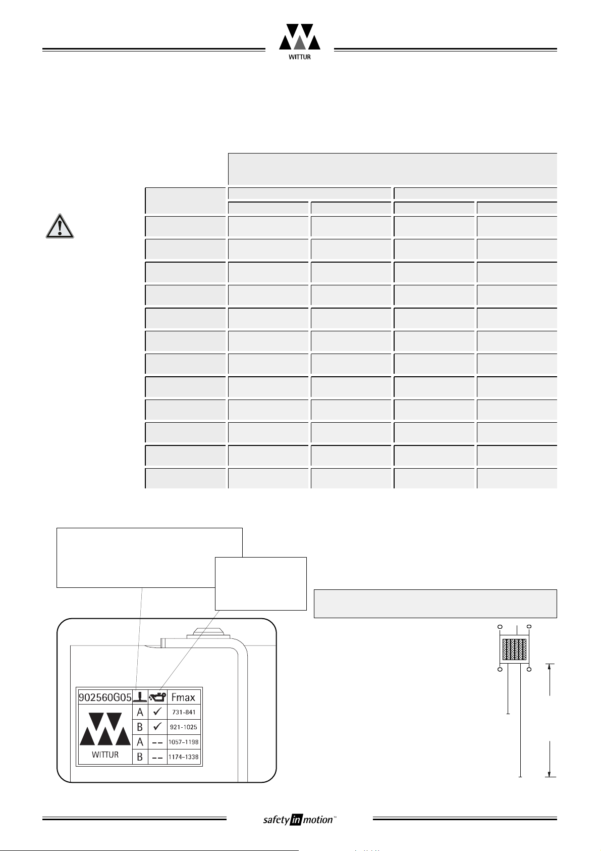
The Type marking is located on the guide plate
(on the front side of the safety gear). The range of
use is stated on a separate sticker (Data label)
nearby on the side of the body. Additionaly a type
label and a identification label are supplied which
are to glue at the housing.
The data on the marking plate and the da-
ta label must be compared with ordering
paper and the project documents.
The Marking gives following data:
• Type term of the safety gear
• Type test designation
• Manufacturing date
• Registration number
(serial number of WITTUR manufacturing)
• Load range - Product code (see chapter 2.3)
• Guide rail nose thickness
• Data label
2 Name plate, designation, identification
Type test designation and
CE-label
Load range
Product code
Registration number
Guide rail thickness
Type term
Data label
incl. LOGO
Manufacturing date
2.1 abelling according to EN81 (CE)

additional Type label for housing:
2.2 abelling according to GOST R 53780 (Russia)
or GOST R53780 the same labelling is used as for EN81.
Additionaly the EAC-Label is supplied:
!"! ##$
%#&'&(# ")%
$$$$""
*+*
,&##%(#%&(+
-./0 1(
2 /0*
#/ 3
&
Blatt/
sheet
D729MGB.007
Datum/
date
23.05.2007
Stand/
version
E-05.04.2016
Geprüft/
approved
WAT/MZE
Änderungen vorbehalten! Subject to change without notice!
Progressive Safety Gear
USG-25P
Operating Instructions
Type term
Load range - Product coed
Serial number
Order Number / Elevator number
(refer to delivery or order sheet)
Manufacturing date
Type-examination
number acc. to EN81
and CE-label
Mass to be gripped Guide rail thickness
Blatt/
sheet
D729MGB.008
Datum/
date
23.05.2007
Stand/
version
G-07.05.2018
Geprüft/
approved
WAT/MZE
Änderungen vorbehalten! Subject to change without notice!
Progressive Safety Gear
USG-25P
Operating Instructions
Rail type (manufacturing method)
acc. DIN ISO 7465 (z.B. T89/A):
A - drawn
B - machined
Rail condition:
Poiled
-- not oiled (dry)
Explanation to Data label:
Calculation method Fmax:
2.3 Range of use
K+Q+T
M1
Fahrhöhe
Travel
M2
max mass to be gripped
K = mass of the car
Q = nominal load
T = mass of the car frame
M1 = mass of travelling cable
M2 = mass of compensation rope/-chain
M = M1 + M2
max = K+Q+T+0,375xM=____kg
P masses of the empty car and components supported by the car,
i.e. part of the travelling cable, compensating ropes/chains (if any)
Q Nominal load
Product code
902560 G01
oiled
drawn (A) machined (B)
dry
drawn (A) machined (B)
650 ... 731 720 ... 809
902560 G02 732 ... 825 810 ... 912
902560 G03 826 ... 932 913 ... 1033
902560 G04 933 ... 1056 1034 ... 1173
902560 G05 1057 ... 1198 1174 ... 1338
902560 G06 1199 ... 1361 1339 ... 1531
902560 G07 1362 ... 1550 1532 ... 1759
902560 G08 1551 ... 1768 1760 ... 2028
902560 G09 1769 ... 2020 2029 ... 2346
902560 G10 2021 ... 2313 2347 ... 2600
465 ... 482 622 ... 679
483 ... 553 680 ... 748
554 ... 635 749 ... 828
636 ... 730 829 ... 920
731 ... 841 921 ... 1025
842 ... 969 1026 ... 1148
970 ... 1117 1149 ... 1291
1118 ... 1290 1292 ... 1458
1291 ... 1490 1459 ... 1653
1491 ... 1723 1654 ... 1881
902560 G11 2314 ... 26001724 ... 1995 1882 ... 2150
902560 G12 1996 ... 2310 2151 ... 2466
max (P+Q) [kg]
according to guide rail manufact. type & surface condition
The ±7,5% clause
according EN81-50 /
5.3.4 must not be
used.

Blatt/
sheet
D729MGB.009
Datum/
date
23.05.2007
Stand/
version
G-07.05.2018
Geprüft/
approved
WAT/MZE
Änderungen vorbehalten! Subject to change without notice!
Progressive Safety Gear
USG-25P
Operating Instructions
3.1 Mounting to the car frame
In accordance to the delivery content the manner
of how to mount it to the car frame is deviating:
• Mounting with flat bars (see chapter 3.1.1)
(e.g. integrated directly to the upright)
• Safety gear with housing (see ig.1)
• If mounting method is different, additional
documentation in included in delivery
In general:
Brake shoe and guide rail must be verti-
cally and horizontally lined up in parallel!
The following malfunction of the safety
gear may appear because of inaccurate
mounting:
• unintended gripping of the Roller
• no 100% braking extent
When mounting the safety gear, observe
the position of the overspeed governor
rope. The position of the lifting lever of
the rope at the safety gear cannot be
changed if the safety gear is built in.
<90°
<90°
ig. 1: Alignment
<90°
3 Installation and adjustment
Inhaltsverzeichnis
Andere WITTUR Sicherheitssensor Handbücher


