WPT POWER PILOTLESS Bedienungsanleitung


Page 2of 39 WIM-TD-002_C
Contents
Signal Words & Definitions
1.0 Introductions
1.1 Product Description
2.0 Exploded Views of Basic Units & Parts List for:
•“C” Style Clutch assembly
•“SP” Style Clutch assembly
3.0 Installation
3.1 Requirements for Proper Operation and Service Life
3.2 Outboard Support
3.3 Driving Ring
3.4 Installing the Unit
3.5 Clutch Adjustment
4.0 Operation
5.0 Disassembly
6.0 Assembly
7.0 Maintenance
7.1 Maintenance Schedule
8.0 General Storage Guidelines
9.0 Tables
•Speed and Size Availability
•SAE Flywheel & Housing Dimensions
•“C” & “SP” Style Lubrication Schedule
•Bolt Torque Values
10.0 Appendices
Appendix A - General
Sideload Information
OEM Clutch Pack Installation & Maintenance instructions
11.0 Trouble shooting guide

Page 3of 39 WIM-TD-002_C
Signal Words & Definitions
Throughout this manual there are several safety messages that must be read and
adhered to in order to prevent
possible loss of equipment and/or personal injury and
/or loss of life. The three signal words are “Danger”, “Warning” and
“Caution”. They are
used to indicate the severity of the hazard and are preceded by a safety alert symbol.
“Danger” - Denotes the most serious
injury hazard and is used when serious injury or death
WILL result from misuse or failure to follow the specific
instructions set forth in this manual.
“Warning” - Denotes when serious
injury or death MAY result from misuse or failure to
follow the specific instructions set forth in this manual.
“Caution” - Denotes when injury or
product or equipment damage may result from the
misuse or failure to follow the specific instructions set
forth in this manual.

Page 4of 39 WIM-TD-002_C
1.0 Introduction
Warning
Forward this manual to the person or persons responsible for
the installation and/or operation and/or maintenance of the
product described herein. Without access to this information,
faulty installation, operation and/or maintenance may occur,
which could result in equipment damage, personal injury and
even death.
Warning
Read these instructions thoroughly and review until you fully
understand all warnings and hazards before proceeding with
the work described in this manual. Failure to follow the
instructions in this manual can result in unreasonable exposure
to hazardous conditions and/or personal injury and/or death.
Warning
Use of improper tools and/or methods when installing or
servicing this unit can result in accidents causing injury and/or
death. Adequate lifting points are provided to safely handle only
the individual unit components. Lifting and handling of the
assembled will require the use of alternate methods.

Page 5of 39 WIM-TD-002_C
1.1 PRODUCT DESCRIPTION
The WPT Pilotless™ Mechanical Power Take-Off (PTO) consists of a lever-actuated clutch with a shaft
and bearings mounted in a rigid housing. The mechanical PTO is designed for inline and sideload
applications on all internal combustion engines with standard SAE industrial flywheel and flywheel housing
dimensions.
WPT mechanical PTO’S fit standard SAE housing sizes #6 thru #0. Various units are available in variety of
sizes and quantities of friction discs. Two bearings are used to distribute the applied load. Two types of
mechanism styles are available in the WPT mechanical PTO’s “C” & “SP”. WPT has a sliding sleeve
assembly using a sealed ball bearing.
WPT mechanical PTO’s nomenclatures are interpreted as such, “314 Mechanical PTO” indicates that there
are three 14” diameter Center Plates.
The WPT PTO is the most rugged PTO available on the market today. Follow the procedures detailed in
this Installation Maintenance Manual for years of service.
When performing installation and maintenance functions, refer to the drawings in this manual on pages 6
thru 13. The references on the drawings in this manual DO NOT correspond to the references on the
assembly drawing and Bill of Materials. Do not use the item numbers from the drawing in this manual for
ordering parts.
Recommended spare parts should be stocked by the customer. This will greatly reduce the possibility of
costly
downtime. Most wear items are normally stocked at the factory or local distributor and can be
shipped quickly from stock. When ordering parts, use the part numbers from the Bill of Materials supplied
with this unit. Also, please include the part number and the serial number from the unit itself, this
information will be found on the metal hand hole cover on the bell housing (see example below). Your
WPT Distributor can provide a copy of the Bill of Materials if the one provided should become lost.
Example Only, reference nameplate on PTO for correct information.
.

Page 6of 39 WIM-TD-002_C
2.0 EXPLODED VIEWS
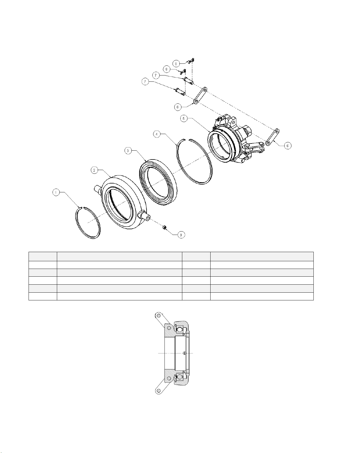
“C”Style Ball Bearing sliding sleeve assembly
Available in sizes 6”- 10”
Item
Description
Item
Description
1
Retaining Ring
6
Clevis Pin
2
Collar
7
Clevis Pin
3
Ball Bearing
8
Link
4
Retaining Ring
9
Cotter Pin
5
Sliding Sleeve

Page 7of 39 WIM-TD-002_C
CLUTCH PACK
“C”Style Ball Bearing Assembly available in sizes 6”- 10”
Item
Description
Item
Description
1
Sliding Sleeve Assembly
5
Spring
2
Adjustment Link Assembly
6
Hub & Backplate
3
Floating Plate
7
Pin
4
Friction Disc

Page 8of 39 WIM-TD-002_C
PTO ASSEMBLY
“C”Style Ball Bearing Assembly available in sizes 6”- 10”
7”PTO Shown
Item
Description
Item
Description
1
Nut
11
Clutch Key
2
Washer
12
Shaft
3
Clutch Pack
13
Output Key
4
Driving Ring
14
Bearing
5
HHCS
15
External Retainer Ring
6
Bearing Retainer
16
Cap
7
Hand Lever Assembly
17
Grease zerk
8
Bellhouse
18
Yoke Assembly
9
Nameplate
19
Key, Woodruff
10
Bearing
20
Operating Shaft

Page 9of 39 WIM-TD-002_C
“C”Style Ball Bearing Assembly available in sizes 6”- 10”
“C” Style
The “C” style sliding assembly utilizes a sealed ball bearing design. Friction disc sizes range from 6” to 10”
with our 1 plate, 2 plate or 3 plate options. WPT PTOs meet the mounting requirements of SAE J617 and
SAE J620.
Page 10 of 39 WIM-TD-002_C
SLIDING SLEEVE ASSEMBLY
“SP”Style Ball Bearing assembly available in sizes 11”- 14”
Item
Description
Item
Description
1
Retainer Ring (Inner)
6
Link
2
Collar
7
Clevis Pin
3
Sealed Ball Bearing
8
Cotter Pin
4
Retainer Ring (Outer)
9
Plug
5
Sliding Sleeve
Inhaltsverzeichnis


