Y-cam Camera Bedienungsanleitung

Y-cam Shell
Assembly Instrucons
English - Français - Deutsch
Italiano - Español - Nederlandse
Package Contents
A) x 3
B) x 3
C) x 4
D) x 4
E) x 1
F) x 1

12
34
5

"
"
910
6
78
For Y-cam Knight or Y-cam Black :

For Y-cam White :
A
A
8w7w
11
C) x 4

15
12
13
14
D) x 4
16
17
Y-cam Soluons Ltd
3 Dee Road
Richmond
Surrey TW9 2JN
United Kingdom
Email: support@y-cam.com
Web: hp://www.y-cam.com

Y-cam Shell Assembly Instrucons - English
Package Contents
A) x 3 – Stainless Steel Screws for Wall Mount Bracket
B) x 3 – Wall plug for Wall Mount Bracket
C) x 4 – Screws for Camera holding Plate (internal)
D) x 4 – Rubber Plugs
E) x 1 – Hex Key
F) x 1 – Y-cam Shell external enclosure
IMPORTANT
PLEASE INSPECT THE SEALS CAREFULLY WHEN ASSEMBLING THE Y-CAM SHELL SINCE AN INCORRECTLY SEATED
SEAL WILL ALLOW MOISTURE TO PENERTATE THE HOUSING AND DAMAGE THE CAMERA. THIS WILL ALSO VOID THE
WARRANTY OF BOTH THE HOUSING AND THE CAMERA.
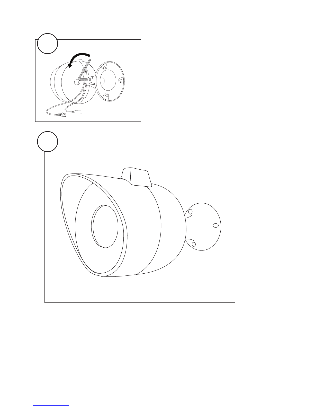
• Using the supplied Hex Key, loosen the wall mounng bracket to allow easy access to the two screws holding the
back plates. (Fig 1)
• Unscrew the two screws (Fig 2) holding the curved back plates and remove the plates. (Fig 3 & 4)
• Remove the four screws holding the front to the main body of the Y-cam Shell (Fig 5)
• Carefully separate the two parts. (Fig 6)
• Connect the network and power cable (Fig 12)
• Carefully assemble the two halves back together (Fig 13) making sure that the rubber seal is seated properly and
that no part of the seal is pinched or out of place. (PLEASE INSPECT THE SEAL CAREFULLY SINCE AN INCORRECTLY
PLACED SEAL WILL ALLOW WATER OR MOISTURE TO LEAK IN AND DAMAGE THE CAMERA)
• Screw back the 4 screws removed in step 3 (Fig 14) and insert the rubber plugs in the screw holes.
• Place the two curved back plates in place and ghten the screws (Fig 15)
• Tighten the hex screw to the desired posion (Fig 16) and inspect the housing (Fig 17) making sure that both seals
(front and middle) are both in place, seated correctly and not pinched.
For Y-cam Knight or Y-cam Black :
• Remove the four screws holding the front dome
(Fig 7)
• Remove the front dome making sure that the
rubber seal under the dome stays in its place. (Fig 8)
• Insert the Y-cam Black or Knight in the front part of
the housing, making sure that the camera dome is
seated properly on the front seal. (Fig 9)
IMPORTANT
PLEASE INSPECT THE SEALS CAREFULLY WHEN
ASSEMBLING THE Y-CAM SHELL SINCE AN
INCORRECTLY SEATED SEAL WILL ALLOW MOISTURE
TO PENERTATE THE HOUSING AND DAMAGE THE
CAMERA.
• Insert the holding plate with side B facing outwards
(Fig 10) and ghten the plate using the 4 supplied
screws (item C in package contents) (Fig 11)
For Y-cam White :
• Insert the Y-cam White in the front part of the
housing. (Fig 7w)
• Insert the holding plate with side A facing outwards
(Fig 8w) and ghten the plate using the 4 supplied
screws (item C in package contents) (Fig 11).

Y-cam Shell Instrucons de Montage - Français
Contenu de l’emballage
A) x 3 – Vis en acier inoxydable pour support d’installaon murale
B) x 3 – Chevilles pour support d’installaon murale
C) x 4 – Vis de la plaque (interne) de xaon de la caméra
D) x 4 – Bouchons en caoutchouc
E) x 1 – Clé hexagonale
F) x 1 – Boîer externe Y-cam Shell
IMPORTANT
VEUILLEZ INSPECTER ATTENTIVEMENT LES JOINTS LORSQUE VOUS MONTEZ LA Y-CAM SHELL. UN JOINT MAL
AJUSTE PERMETTRA A L’HUMIDITE DE S’INFILTRER DANS LE BOÎTIER ET D’ENDOMMAGER LA CAMERA. CECI
PROVOQUERA EGALEMENT L’ANNULATION DE LA GARANTIE DE LA COQUE ET DE LA CAMERA.
• Desserrez le support d’installaon murale à l’aide de la clé hexagonale fournie an de permere un accès facile
aux deux vis qui mainennent les plaques arrière (Fig. 1).
• Desserrez les deux vis (g. 2) qui mainennent les plaques arrière incurvées puis rerez ces dernières (Fig. 3 & 4).
• Rerez les quatre vis qui mainennent l’avant avec le corps principal de la Y-cam Shell (Fig. 5).
• Séparez délicatement les deux pares (Fig. 6).
• Branchez les câbles du réseau et de l’alimentaon (Fig.12).
• Assemblez précauonneusement les deux moiés (Fig.13) en vous assurant que le joint en caoutchouc soit
bien en place et qu’aucune pare de ce dernier ne soit écrasée ou mal posionnée (VEUILLEZ INSPECTER
ATTENTIVEMENT LE JOINT CAR UN JOINT MAL AJUSTE PERMETTRA A L’EAU OU A L’HUMIDITE DE S’INFILTRER
DANS LA CAMERA ET DE L’ENDOMMAGER).
• Revissez les 4 vis que vous avez rerées à l’étape 3 (Fig.14) et insérez les bouchons en caoutchouc dans les orices
des vis.
• Placez les deux plaques arrière incurvées et serrez les vis (Fig.15).
• Serrez la vis hexagonale dans la posion voulue (Fig.16) et inspectez le boîer (g.17) en vous assurant que les
deux joints (le joint avant et le joint central) soient bien en place et ne soient pas écrasés.
For Y-cam Knight or Y-cam Black :
• Rerez les quatre vis qui mainennent le dôme
avant (Fig. 7).
• Rerez le dôme avant en vous assurant que le
joint en caoutchouc situé sous le dôme reste bien en
place. (Fig 8)
• Insérez la Y-cam Black ou Knight dans l’élément
avant du logement, en vous assurant que le dôme
de la caméra soit bien posionné sur le joint avant
(Fig. 9).
IMPORTANT
VEUILLEZ INSPECTER ATTENTIVEMENT LES JOINTS
LORS DU MONTAGE DE LA Y-CAM SHELL CAR UN
JOINT MAL AJUSTE PERMETTRA A L’HUMIDITE DE
PENETRER DANS LE BOÎTER ET D’ENDOMMAGER LA
CAMERA
• Insérez la plaque de support avec la face B dirigée
vers l’extérieur (Fig. 10) et serrez la plaque à l’aide
des 4 vis fournies (arcle C dans le Contenu de
l’emballage) (Fig. 11).
For Y-cam White :
• Insérez la Y-cam White dans la pare avant de son
logement (Fig. 7w)
• Insérez la plaque de souen avec la face A dirigée
vers l’extérieur (Fig. 8w) puis serrez la plaque à
l’aide des 4 vis fournies (arcle C dans le Contenu de
l’emballage) (Fig. 11).

Y-cam Shell Anweisungen zum Zusammenbau - Deutsch
Verpackungsinhalt
A) x 3 – Rosreie Stahlschrauben für die Wandhalterung
B) x 3 – Dübel für die Wandhalterung
C) x 4 – Schrauben für die Kamera-Halteplae (intern)
D) x 4 – Gummistopfen
E) x 1 – Inbusschlüssel
F) x 1 – Externes Gehäuse für Y-cam Shell
WICHTIG
BITTE ÜBERPRÜFEN SIE BEI DER MONTAGE SORGFÄLTIG DIE DICHTUNGEN DER Y-CAM SHELL, DA EINE FALSCH
ANGEBRACHTE DICHTUNG FEUCHTIGKEIT IN DAS GEHÄUSE EINDRINGEN LÄSST UND DIE KAMERA BESCHÄDIGT.
DIES FÜHRT AUCH ZUM ERLÖSCHEN DER GARANTIE FÜR GEHÄUSE UND KAMERA.
• Lösen Sie mit dem mitgelieferten Inbusschlüssel die Wandhalterung, um leichter an die beiden Schrauben zu
gelangen, welche die hinteren Plaen halten. (Abb. 1)
• Lösen Sie die beiden Schrauben (Abb. 2), welche die hinteren Gehäuseschalen halten und enernen diese. (Abb.
3 und 4)
• Enernen Sie die vier Schrauben, welche das Vorderteil auf der Basis der Y-cam Shell halten. (Abb. 5)
• Trennen Sie vorsichg die zwei Teile. (Abb. 6)
• Schließen Sie das Netzwerk- und Netzkabel an (Abb. 12).
• Setzen Sie vorsichg beiden Hälen wieder zusammen (Abb. 13) und achten Sie darauf, dass die Gummidichtung
richg sitzt und dass kein Teil der Dichtung eingeklemmt wurde oder verrutscht ist. (BITTE ÜBERPRÜFEN SIE
SORGFÄLTIG DIE DICHTUNG, DA EINE NICHT RICHTIG ANGEBRACHTE DICHTUNG WASSER ODER FEUCHTIGKEIT IN
DAS GEHÄUSE EINDRINGEN LÄSST UND DIE KAMERA BESCHÄDIGT.)
• Ziehen Sie wieder die 4 Schrauben fest, die Sie in Schri 3 enernt haben(Abb. 14) und stecken Sie die
Gummistopfen in die Schraubenlöcher.
• Setzen Sie die beiden hinteren Gehäuseschalen ein und ziehen Sie die Schrauben fest (Abb. 15)
• Ziehen Sie die Inbusschraube in der gewünschten Stellung fest (Abb. 16). Überprüfen Sie das Gehäuse (Abb. 17)
und achten darauf, dass die beiden Dichtungen (vorne und in der Mie) richg an ihrem Platz sitzen und nicht
eingeklemmt sind.
For Y-cam Knight or Y-cam Black :
• Enernen Sie die vier Schrauben, welche die
vordere Haube halten. (Abb. 7)
• Enernen Sie die vordere Haube und achten
darauf, dass die Gummidichtung unterhalb der
Haube an ihrem Platz bleibt. (Fig 8)
• Setzen Sie die Y-cam Black oder Knight in vorderen
Teil des Gehäuses ein und achten darauf, dass die
Kamerahaube gut auf der vorderen Dichtung sitzt.
(Abb. 9)
WICHTIG
BITTE ÜBERPRÜFEN SIE SORGFÄLTIG DIE
DICHTUNGEN BEIM ZUSAMMENBAU DER Y-CAM
SHELL, DA EINE NICHT RICHTIG ANGEBRACHTE
DICHTUNG FEUCHTIGKEIT IN DAS GEHÄUSE
EINDRINGEN LÄSST UND DIE KAMERA BESCHÄDIGT.
• Setzen Sie die Halteplae mit Seite B nach
außen ein (Abb. 10) und befesgen Sie die Plae
mit den 4 mitgelieferten Schrauben (Arkel C im
Verpackungsinhalt) (Abb. 11).
For Y-cam White :
• Setzen Sie die Y-cam White in vorderen Teil des
Gehäuses ein. (Abb. 7w)
• Setzen Sie die Halteplae mit Seite A nach
außen ein (Abb. 8w) und befesgen Sie die Plae
mit den 4 mitgelieferten Schrauben (Arkel C im
Verpackungsinhalt) (Abb. 11).

Y-cam Shell Istruzioni di Montaggio - Italiano
Contenuto della confezione
A) x 3 – Vi in acciaio inox per supporto per montaggio a parete
B) x 3 – Tasselli per supporto per montaggio a parete
C) x 4 – Vi per piastra di supporto per videocamera ( interna )
D) x 4 – Cappucci in gomma
E) x 1 – Brugola
F) x 1 – Struura esterna Y-cam Shell
IMPORTANTE
FARE PARTICOLARE ATTENZIONE IN FASE DI MONTAGGIO DELLA Y-CAM SHELL PERCHÉ IL MONTAGGIO NON
CORRETTO DI UNA GUARNIZIONE CONSENTE ALL’UMIDITÁ DI PENETRARE NELLA STRUTTURA E DANNEGGIARE
LA VIDEOCAMERA, CAUSANDO IL DECADIMENTO DELLA GARANZIA SIA DELL’ALLOGGIAMENTO CHE DELLA
VIDEOCAMERA.
• Ulizzando la brugola in dotazione, allentare il supporto per montaggio a parete per consenre un facile accesso
alle due vi che ssano le piastre posteriori. (Fig 1)
• Svitare le due vi (Fig 2) che ssano le piastre posteriori curve, quindi rimuovere le piastre. (Fig 3 & 4)
• Rimuovere le quaro vi che ssano la parte anteriore al corpo principale della Y-cam Shell. (Fig 5)
• Separare con aenzione le due par. (Fig 6)
• Eeuare i collegamen di alimentazione e della rete (Fig 12).
• Rimontare con aenzione le due par (Fig 13) accertandosi che la guarnizione in gomma si trovi in posizione
correa e che nessuna parte della guarnizione sia schiacciata o non in sede. (CONTROLLARE LA GUARNIZIONE
CON ATTENZIONE PERCHÉ IL MONTAGGIO NON CORRETTO DELLA GUARNIZIONE CONSENTE ALL’UMIDITÁ DI
PENETRARE NELLA STRUTTURA E DANNGGIARE LA VIDEOCAMERA)
• Riavvitare le 4 vi rimosse come indicato al punto 3 (Fig 14) ed inserire i cappucci in gomma nei fori delle vi.
• Riposizionare le due piastre posteriori curve, quindi serrare le vi (Fig 15)
• Serrare le vite esagonale nella posizione desiderata (Fig 16) e controllare la struura (Fig 17) accertandosi che
entrambe le guarnizioni (anteriore e mediana) si trovino entrambe in posizione, siano montate correamente e
non siano schiacciate da altre par.
For Y-cam Knight or Y-cam Black :
• Rimuovere le quaro vi che ssano la cupola
anteriore. (Fig 7)
• Rimuovere la cupola anteriore accertandosi che la
guarnizione in gomma si trovi in posizione. (Fig 8)
• Inserire Y-cam Black o Knight nella parte anteriore
della struura, accertandosi che la cupola della
videocamera si trovi in posizione correa sulla
guarnizione anteriore. (Fig 9)
IMPORTANTE
FARE PARTICOLARE ATTENZIONE IN FASE DI
MONTAGGIO DELLA STRUTTURA DELLA Y-CAM
SHELL PERCHÉ IL MONTAGGIO NON CORRETTO
DELLA GUARNIZIONE CONSENTE ALL’UMIDITÁ DI
PENETRARE NELLA STRUTTURA E DANNGGIARE LA
VIDEOCAMERA.
• Inserire la piastra di sostegno con il lato B rivolto
verso l’esterno (Fig 10) e serrare la piastra ulizzando
le 4 vi in dotazione. (arcolo C nella lista del
contenuto della confezione) (Fig 11)
For Y-cam White :
• Inserire la Y-cam White nella parte anteriore della
struura. (Fig 7w)
• Inserire la piastra di supporto con la il lato A
rivolto verso l’esterno (Fig 8w) e serrare la piastra
ulizzando le 4 vi in dotazione (arcolo C nella lista
del contenuto della confezione) (Fig 11).
Andere Handbücher für Camera
1
Dieses Handbuch passt für folgende Modelle
1
Inhaltsverzeichnis
Sprachen:


