YSI EcoMapper Bedienungsanleitung

Autonomous Underwater Vehicle
Description and General Information 1
Safety and Limitations 2
VectorMap 3
Operation 4
UVC 5
Calibration 6
Maintenance and Repair 7
Appendices A-C
A. Install/Update Software B. Run SonarMosaic
C. Safety Tow Float

1 Description and General lnformation
1.1 Overview 2
1.2 Exterior Features 3
1.21 Looking at the Vehicle ........................................ 3
1.22 Antenna ........................................................... 4
1.23 Nose ...............................................................4
1.24 Body ............................................................... 5
1.25 Tail .................................................................. 6
1.26 Safety Tow Float ................................................ 7
1.27 How the EcoMapper Navigates .......................... 7
1.3 Applications 7
1.4 Specifications 8
1.41 Physical Dimensions .......................................... 8
1.42 Onboard Electronics .......................................... 8
1.43 Mobility and Endurance .....................................8
1.44 Standard Sensors .............................................. 8
1.45 Optional Sensors .............................................. 8
1.46 Derived Parameters ........................................... 8
Autonomous Underwater Vehicle

2
1.1 Overview
e YSI EcoMapper is a one-man deployable, Autonomous Underwater Vehicle (AUV) designed to collect
bathymetry and water quality data. e submarine-like vehicle follows a programmed course and employs
sensors mounted in the nose to record pertinent information. Once the vehicle has started its mission, it
operates independently of the user and utilizes GPS waypoints and “Dead Reckoning” navigation to complete
its programmed course. roughout the course, the vehicle constantly steers toward the line drawn in the mission
planning soware (VectorMap), essentially following a more accurate “road” of coordinates instead of transversing
waypoint-to-waypoint. When equipped, the vehicle also uses a Dopplar Velocity Log (DVL) to increase its underwater
navigation accuracy. Upon completing its mission, the vehicle uses Windows® Remote Desktop to relay the collected
data via WiFi connection, facilitated by the Communications Box, to the user’s computer.
Nose
Handle
Weight Track
DVL
Sensor Guard
Communications Box
1.1

3
1.2 Exterior Features
1.21 Looking at the Vehicle
e AUV appears identical on both sides. When you view the vehicle, several exterior features become
immediately visible. Viewing the AUV from the port side reveals the plastic nose cone containing the instrument
cluster on your le (at the front of the vehicle) with the tail section on your right. e transport handle is located
on top of the carbon-ber hull on the opposite side of the xed buoyancy weights and pinger, which are located on the
bottom of the hull. e aluminum tail section of the vehicle houses the vehicle’s motor and connects to the control ns
and propeller. e WiFi and GPS antennae are housed in the clear plastic tower on top of the rear half of the vehicle.
Antenna
Tail
Side-Scan Sonar
Hull
1.2

4
1.22 Antenna
In addition to the WiFi and GPS antennae, the tower houses a two-pin connector used to charge the vehicle. e tower
also contains a variety of LEDs with specic functions.
A. Solid green: navigational, visible on starboard side
B. Solid red: navigational, visible on port side
C. Solid white: navigational, visible from rear
D. Flashing yellow: indicates battery charging (solid yellow indicates full charge. e light is on only when
connected to AC charger)
D
DA
B
B
C
C
1.23 Nose
e nose cone contains all of the vehicles external water quality sensors. It also contains the depth-sounder, pressure
sensor and compass. Water quality sensors are housed inside the screw-on protective nose cone on the front of the
AUV and are eld-replaceable. A pressure sensor, detecting the depth from the surface, and an altimeter, a depth-
sounding sonar that detects the vehicle’s height from the bottom, are also housed in the nose section. A vacuum port
located on top of the nose cone is used to check the internal pressure and seals of the AUV.
Sensor Guard Vacuum Port
Altimeter
WQ Sensors Inside
Compass Inside
Integrated Pressure Sensor
DVL
1.2

5
1.24 Body
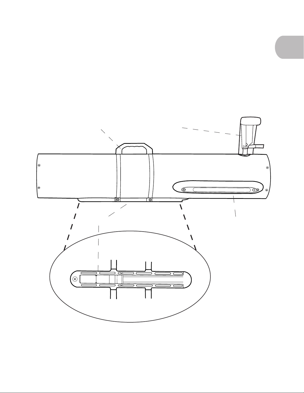
e transport handle, located approximately half-way down the hull of the vehicle, is used to carry the vehicle when
not in its travel crate. Opposite the handle, on the bottom of the vehicle, are xed buoyancy weights in a track,
which are moved and trimmed to balance the vehicle and adjust its buoyancy to correspond with water density
(inuenced by salinity. Although pressure inuences density, you cannot trim the vehicle based on pressure.). A
location pinger is also located on the weight track of the vehicle, which sends a high-frequency signal that can be
detected by a special receiving unit in the event that the AUV is lost. Optional side-scan sonar is located to the rear
of the handles on the bottom half of the vehicle.
1.2
Handle
Side-Scan Sonar
Antenna
Weight Track

6
1.25 Tail
e tail section is the only exterior section of the vehicle made of metal in order to accommodate the torque of the
electric drive motor. Two zinc patches, located on the bottom of the tail section, operate in a sacricial capacity.
In the event that the aluminum is scratched, the zinc corrodes instead of the aluminum. Four control planes are
operated independently to inuence pitch, roll, and yaw. e vehicle’s two-bladed propeller is located at the rear
of the vehicle inside a Kort nozzle. All ns and the propeller are eld replaceable.
1.2
Zinc Patches
Control Planes
Propeller
Kort Nozzle
Kort Nozzle

7
1.26 Safety Tow Float
An optional safety tow-oat can be pulled behind the vehicle attached to the two-pin connector at the base of the
antennae. e Safety Tow Float system includes a processor, power/tow cable, acoustic location pinger, depth sensor,
and a large buoyancy bag, which uses a rechargeable CO2 cartridge for ination, to immediately surface the
vehicle in the event of an emergency condition. Read more about the Safety Tow Float in Appendix C.
1.27 How the EcoMapper Navigates
e EcoMapper utilizes a variety of methods to navigate both above water and below water. Every vehicle is equipped
with a GPS navigation system and dead-reckoning; doppler velocity logs (DVLs) can be purchased and equipped as an
option to increase the accuracy of a vehicle’s navigation.
For any vehicle, the most accurate navigation occurs on the surface using GPS navigation. e vehicle follows the
line drawn between waypoints in the EcoMapper’s mission-planning soware (VectorMap) to drive where the user
programs it to go. When an AUV without DVL dives, it uses a depth-sounding sonar and pressure sensor to determine
its depth. e vehicle then uses a combination of its digital compass and propellor-rotation counting to calculate the
distance and direction traveled underwater. If the vehicle is pushed by a current, it self corrects once it reaquires a GPS
signal on the surface.
While a DVL-equipped vehicle is on the surface, it also uses GPS to navigate. However, when it dives, it does not
switch to dead-reckoning. If the vehicle is within approximately 300 feet of the bottom, it will use its DVL to bottom-
track with an array of sonars. Depending on the individual vehicle, DVL-equipped AUVs emit six to ten sonar beams,
which reect from the bottom. e vehicle then receives and interprets the signal to determine if it has been pushed
o course by a current or other similar force. e vehicle can then correct itself en route by driving constantly back to
the programmed line. If the vehicle loses its bottom lock, it will switch to water-tracking to navigate. Water-tracking
utilizes the same principles as bottom-tracking, only it relies on sonar signals received from beams reected from
particulate in the water. If a vehicle loses both bottom-tracking and water-tracking, it will utilize dead-reckoning until
it re-establishes one of the more accurate methods. An AUV can also use these signals to derive its speed and more
accurate depth from bottom.
1.3 Applications
Potential EcoMapper applications include…
• Baseline Environmental Mapping in freshwater, estuarine or near-coastal environments
• Bathymetric mapping
• Dissolved oxygen studies
• Event monitoring (algal blooms, storm impacts, low dissolved oxygen)
• Non-point source studies
• Point-source dispersion mapping
• Security, search & rescue, inspection
• Shallow water mapping
• ermal dissipation mapping of cooling outfalls
• Trace-dye studies
1.3

8
1.4 Specifications
1.41 Physical Dimensions
• Weight: 45 lbs (20.45 kgs)
• Length, Bow (Front) to Stern (Rear): 60.1 in (152.7 cm)
• Hull Diameter: 5.8 in (14.7 cm)
• Fin-to-Fin: 11 in (27.9 cm)
• Recording speed: 1 Hz
1.42 Onboard Electronics
• Processor: X86
• Soware: Windows XP, GUI-based Navigation Suite Map
• Storage: 80 GB
• WiFi: 802.11g Ethernet
• Energy Source: Rechargeable Lithium-Ion Batteries (Total 600 WHrs or greater than 300 cycles)
• Charge time: 4 hrs
• Navigation: GPS on surface, “Dead Reckoning” and DVL below surface
• Communication: 802.11g Ethernet link on surface
• Motor: 150 Watt electric
• WiFi Communication Range: 200 m
1.43 Mobility and Endurance
• Maximum Depth: 200 (200 m with deep-water sensors)
• Control: Four independent control planes
• Speed: 1-4 knots (maximum of 2 knots on surface)
• Locomotion: Two-bladed propeller
• Battery Endurance: 8 hrs at 2.5 knots
1.44 Standard Sensors
• YSI Conductivity and Temperature Sensors
• Depth from Surface: YSI Depth Sensor
• Height from Bottom: Depth-sounding sonar (altimeter)
• Direction: ree-axis digital compass
1.45 Optional Sensors
• Sonar: Imagenex SportScan side-scan sonar (300 kHz or 330/800 kHz)
• pH/ORP
• ROX™ Optical Dissolved Oxygen
• Turbidity
• Chlorophyll
• Blue-Green Algae (marine or freshwater)
• Rhodamine WT
1.46 Derived Parameters
• Specic Conductance
• Salinity
• Resitivity
• Total dissolved Solids (TDS)
1.4

Autonomous Underwater Vehicle
2 Safety, Limitations and Capabilities
2.1 Safety 10
2.2 Limitations and Capabilities 11
2.21 Environment ................................................... 11
2.22 Depth ............................................................ 11
2.23 Navigation ..................................................... 11
2.24 Velocity .......................................................... 11
2.24 Endurance...................................................... 11
2.25 Deployment .................................................... 11
Inhaltsverzeichnis