YZ Systems DynaPak 2010N Series Bedienungsanleitung

DynaPak2010N
SystemSupport
Manual
ANSI-900
Version05302001ATEXRev.

2
Table Of Contents
1.Introduction 3
2. System Components 3
3. Theory of Operation 4
4. Sampler Location 5
5. Sampler Installation 6
6. Sample Vessel Installation 8
7. Operational Check & Leak Testing 9
8. Sampler Set-Up: time-based
sampling 10
9. Sampler Set-Up: time-based
sampling with the DPS-2 12
10. Sampler Set-Up: proportional-
to-flow sampling 14
11. Sampler Maintenance 18
12. Trouble Shooting 22
13. Diagrams
#1 DP-2000N pump (assembled) 26
#2 DP-2000N pump (exploded) 27
#3 YZ filter regulator (assembled) 28
#4 YZfilterregulator(exploded) 29
#5 LinkPlus 30
#6 DPS-2 31
#7 Z-65controller 32
#8 Z-65installationnotes/wiring
control documentation 33
#9 DuraSite Portable Sample vessel
installation 34
Notes 36
YZSystems,Inc.representsandwarrantsthatforaperiodof3yearsfromreceiptoftheproduct:(1)theproductwillbefreefromdefectsinmaterialsandworkmanship;and(2)theproductwill
performsubstantiallyinaccordancewithproductmanuals,literature,ordocumentation. AnywrittenororalinformationoradvicegivenbyYZrepresentatives,agents,oremployeeswillinnowayincrease
thescopeofthiswarranty. Iftheproductfailstocomplywiththewarrantysetforthherein,YZ'sentireliabilityandthecustomer'sexclusiveremedywillbereplacementoftheproduct(s)or,atYZ'soption,
YZ'sreasonableefforttomaketheproductmeetthewarrantysetforthherein. YZdisclaimsallotherwarranties,eitherexpressedorimplied,includingbutnotlimitedto,impliedwarranties
ormerchantabilityandfitnessforaparticularpurpose,withrespecttotheproduct. Thislimitedwarrantygivesyouspecificlegalrights. Youmayhaveothers,whichvaryfromstatetostate. These
remediesarenotavailableoutsideoftheUnitedStatesandCanada. InnoeventshallYZoritssuppliersbeliableforanydamageswhatsoever(including,withoutlimitation,damagesforlossof
profits,businessinterruption,lossofinformation,orotherpecuniaryloss)arisingoutoftheuseoforinabilitytousetheproduct,evenifYZhasbeenadvisedofthepossibilityofsuchdamages. Information
containedinthisdocumentissubjecttochangewithoutnoticeanddoesnotrepresentacommitmentonthepartofYZSystems,Inc. AllpricesquotedareinU.S.dollars,F.O.B.Snyder,Texas. DynaPak,
SmartSiteandDuraSitearetrademarksofYZSystems,Inc. Allotherproductnamesand/orregisteredtrademarksarethepropertyoftheirrespectiveholders. YZsupportservicesaresubjecttoYZ's
then-currentprices,terms,andconditions,whicharesubjecttochangewithoutnotice. Allpricesandspecifications,ifpublished,aresubjecttochangewithoutnotice.

DynaPak 2010N Version 05302001 ATEX Rev.
YZ Systems, Inc. • 3101 Pollok Drive • Conroe, Texas • USA • 77303 • P: 936.788.5593 • F: 936.788.5720
3
1. Introduction
Congratulations on your purchase of the DynaPak
2010N Series Sampler. You've made a wise
measurement investment for your company.
Before you begin installation, insure that all of the
necessary components are present. You will need
a sample cylinder(s) during the installation. If you
have questions concerning installation/operation,
contact your YZ representative or YZ Customer
Service at 936.788.5593.
2. System Components
The primary components of the DynaPak 2010N
Sampling System are illustrated here.
1949
Factory
System
Approve d
Mutual
Sample Discharge
DynaPak 2000 Pump
Tubing
Purge Valve
Isolation Valve
Sample Discharge
Probe Body Assembly
Note:
Filter/Regulator
YZ SYSTEMS, INC.
3101 POLLOK DRIVE CONROE, TEXAS 77303
Z-65 Controller Cable Entry Fitting Solenoid Valve
Patents 5,152,678; 4,531,895; 4,928,536
Wiring and Pneumatic Tubing Not
Shown For Drawing Clarity
Sample Inlet
8" (20cm)
6" (15cm)
DynaPak 2000N Pump
10 1/2" (27 cm)
8 1/2" (22 cm)
DP-2010N

4
DynaPak 2010N Gas Sampler
The DynaPak 2010N Sampler is a pipeline
mounted system which uses the pneumatically
operated, positive displacement DynaPak 2000N
pump, the Z-65 timer/controller, the YZ filter/
regulator and a low power solenoid valve to obtain
gas samples. The 2010N provides three
modes of operation:
A. Time-based sampling in this mode of
operation, the 2010N extracts a gas sample from
the pipeline at regular time intervals. The volume
of the sample is set by the operator using the
volume adjustment feature of the DP-2000N
pump. The Z-65 controller operates as a recycling
timer, periodically energizing a low power solenoid
valve. Energizing the solenoid valve allows actua-
tion gas to stroke the DP-2000N pump. The rate
at which this occurs is a function of operator input.
Two 10 position switches are used to set the off
time interval. The number of times the solenoid
output is activated is recorded by the onboard LCD
stroke indicator.
B. Time-based sampling with the (Optional)
YZ differential pressure switch (DPS-2)
this mode of operation is similar to the time-based
sampling mode, except that the DPS-2 converts a
differential pressure signal to an electrical signal
that the Z-65 timer uses to determine if flow is
present in the pipeline. In effect, the DPS allows
the Z-65 timer to shut off when flow stops in the
pipeline, and when flow starts again, the ability to
start-up and resume operation.
NOTE: Maximum Pipeline Pressure 1500 psig.
using DPS-2
C. Proportional-to-flow sampling
in this mode of operation, the Z-65 counter
operates as a dividing counter. The Z-65 counter
periodically energizes a low power solenoid valve.
As in the other two modes of operation, this allows
actuation gas to stroke the DP-2000N pump. The
rate at which this occurs is a function of operator
input as well as the host computer or other device
that inputs pulses per volume metered. The two
10-position switches on the Z-65 are used to set
the number of pulses the counter will count before
activating the solenoid output. The number of
times the solenoid output is activated is recorded
by the onboard LCD stroke indicator. Sample
volume is again controlled using the DP-2000N
volume adjustment knob.
In all three modes of operation, the Z-65 timer/
counter operates using a replaceable internal
battery pack. The battery pack condition is
monitored by way of two indicator LEDs. When
the battery pack needs replacement, the red LED
will illuminate when the solenoid output is
activated. If the battery pack is good, the green
LED will illuminate when the solenoid is activated.
The External Power Option can be used in lieu
of the internal battery pack. The External Power
Option (model # EPO-120) consists of an AC to
DC convertor and intrinsically safe barrier to
convert 120 VAC power to 28 VDC to operate the
controller without the use of the internal battery
pack.
The Solar Power Option would be used in lieu of
the internal battery pack. The Solar Power
Option (model #SPO-12) consists of a 5 watt
solar panel with RM-12 charger regulator module
and internal 12V, 5 Amp hour battery pack.
3. Theory of Operation

DynaPak 2010N Version 05302001 ATEX Rev.
YZ Systems, Inc. • 3101 Pollok Drive • Conroe, Texas • USA • 77303 • P: 936.788.5593 • F: 936.788.5720
5
4.1 The sampler should be a minimum of five
pipe diameters from any device which could cause
aerosols or significant pressure drops.
4.2 The sampler should not be located within the
defined meter tube region (AGA 3 manual).
A = The number of unobstructed, straight pipe
diameters upstream (see AGA - 3 manual).
B = The number of unobstructed, straight pipe
diameters downstream (see AGA - 3 manual).
Meter Tube
Optimum Sampler Probe Locations
Differential Pressure Device
5 Ø
Flow
A B 5 Ø
4. Sampler Location

6
5.1 DynaPak 2010N
a. The DynaPak 2010N requires a 3/4" FNPT
pipelineconnection.
b. The DynaPak 2010N sampler should be
mounted vertically in a horizontal run of the
pipeline.
c. The end of the sampler probe should penetrate
the center 1/3rd of the pipeline.
d. The end of the sample probe should be cut
paralleltothe pipeline.
e. Before applying pipeline pressure to the
DynaPak 2010N, ensure that the isolation valve
and purge valve are closed.
f. After pipeline pressure has been applied to the
sampler, check the probe body/pipeline connection
using a liquid leak detector.
CAUTION:
Incorrect operation of valves (over tightening) can
result in damage to the valve components
(isolation valve bonnet assembly) which might
result in the valve stem being screwed out of the
probe body. This of course results in product at
pipeline pressure being vented continually through
this port until this section of the pipeline is shut in.
Be aware of the following procedures and
information.
· DynaPak valves are of soft seat
design and should only be closed
or opened with fingers. No
wrenches should ever be used.
· If a valve will not seal off with
finger tight operation the valve
should have maintenance
performed to allow proper
operation of the valve.
Center 1/3
1/3
1/3
1/3
Center 1/3
1/3
1/3
1/3
5. System Installation
Maximum Pipeline Pressure 2160 psig.

DynaPak 2010N Version 05302001 ATEX Rev.
YZ Systems, Inc. • 3101 Pollok Drive • Conroe, Texas • USA • 77303 • P: 936.788.5593 • F: 936.788.5720
7
5. System Installation
5.2 (Optional)DPS-2:
Maximum Pipeline Pressure 1500 psig
with this option.
a. With the low pressure supply valve and the high
pressure supply valve closed, connect the DPS-2
to the orifice connection tubing.
b. Open the equalization valve.
c. Open the low pressure supply valve or the high
pressure supply valve.
NOTE: Do not open either the low pressure
supply valve or the high pressure supply valve
without ensuring that the equalization valve is
open. Failure to do so may damage the
DPS-2's internal components.
d. Open the other supply valve.
e. Close the equalization valve.
f. Run the free end of the DPS-2 cable through the
cable entry connector located on the upper left
side on the DynaPak 2010N enclosure.
g. Connect the DPS-2 cable as shown in the
diagram.
h. Tighten the cable entry connector, allowing for
enough cable length to open the enclosure.
High Pressure Supply Valve
Orifice Connection
Equalization Valve
Low Pressure Supply Valve
Flow
Low Pressure
High Pressure
Factory
Approved
System
Mutual
Clear
Black
Maximum Pipeline Pressure 1500 psig.
Maximum
Pipeline
Pressure
1500 psig.

8
6.1 Variable pressure/constant volume cylinders.
Spun cylinders may be installed in a horizontal position
on the DynaPak BackRack vessel rack. Avoiding traps
in the line, install stainless steel tubing and fittings from
the sample discharge port of the sampler to the product
end of the sample cylinder.
300cc and 500cc spun cylinders may also be installed
in a vertical position. Piping from the sampler dischage
port to the sample vessel should be arranged so that
liquid traps are not created.
6.2 Variable volume/constant pressure cylinder.
The free-floating piston cylinder (DuraSite) may be
installed in a horizontal position on an optional vessel
rack. Free-floating piston cylinders should NOT be
installed on the DynaPak BackRack vessel rack.
Install 1/8" tubing from the sample discharge port of the
manifold to the product end of the vessel. Avoid traps in
this line.
See diagram #9 for DuraSite portable sample vessel
instructions.
6.3 LinkPlus. Install the optional LinkPlus directly into
the sample discharge port of the sampler. Use
stainless steel tubing and fittings to connect the
LinkPlus outlet to the product end of the sample
cylinder.
6. Sample Vessel Installation

DynaPak 2010N Version 05302001 ATEX Rev.
YZ Systems, Inc. • 3101 Pollok Drive • Conroe, Texas • USA • 77303 • P: 936.788.5593 • F: 936.788.5720
9
7.1 When all of the tubing connections have been
completed, close the purge valve on the front of the
sampler probe body. Open the sample probe supply
valve to allow pipeline pressure into the sampler.
Check all connections using a liquid leak detector.
7.2 Adjust the filter/regulator from the following
ranges:
Pipeline Pressure Actuation Pressure
Under 700 psig (48 Bar) 50 psig (3.5 Bar)
700-1500 psig (48-103 Bar) 65 psig (4.5 Bar)
1500-2160 psig (103-149 Bar) 75 psig (5.2 Bar)
7.3 Turn the stroke adjustment knob on the top of the
pump counterclockwise to set the pump
displacement at .4cc/stroke.
7.4 Move all of the mode switches on the Z-65 to their
off positions.
7.5 Move both timer/counter dials to the 0 position
(00 minutes).
7.6 Move mode switches 1, 2 and 3 to the on position.
The pump will begin stroking once every 2 seconds in
a diagnostic test mode.
7.7 Allow the sampler to operate until the pipeline
pressure plus 100 psi (6.9 Bar) is achieved at the
sample discharge.
7.8 Return the mode switches to their off positions.
7.9 Check all connections from the sampler
discharge to the connection on the sample cylinder
using a liquid leak detector.
7.10 If no leaks are found, the pump and tubing
should be considered tested and functional.
NOTE:Blackindicates
theswitchposition.
Mutual
System
Approved
Factory
7. Operational Check & Leak Testing
10
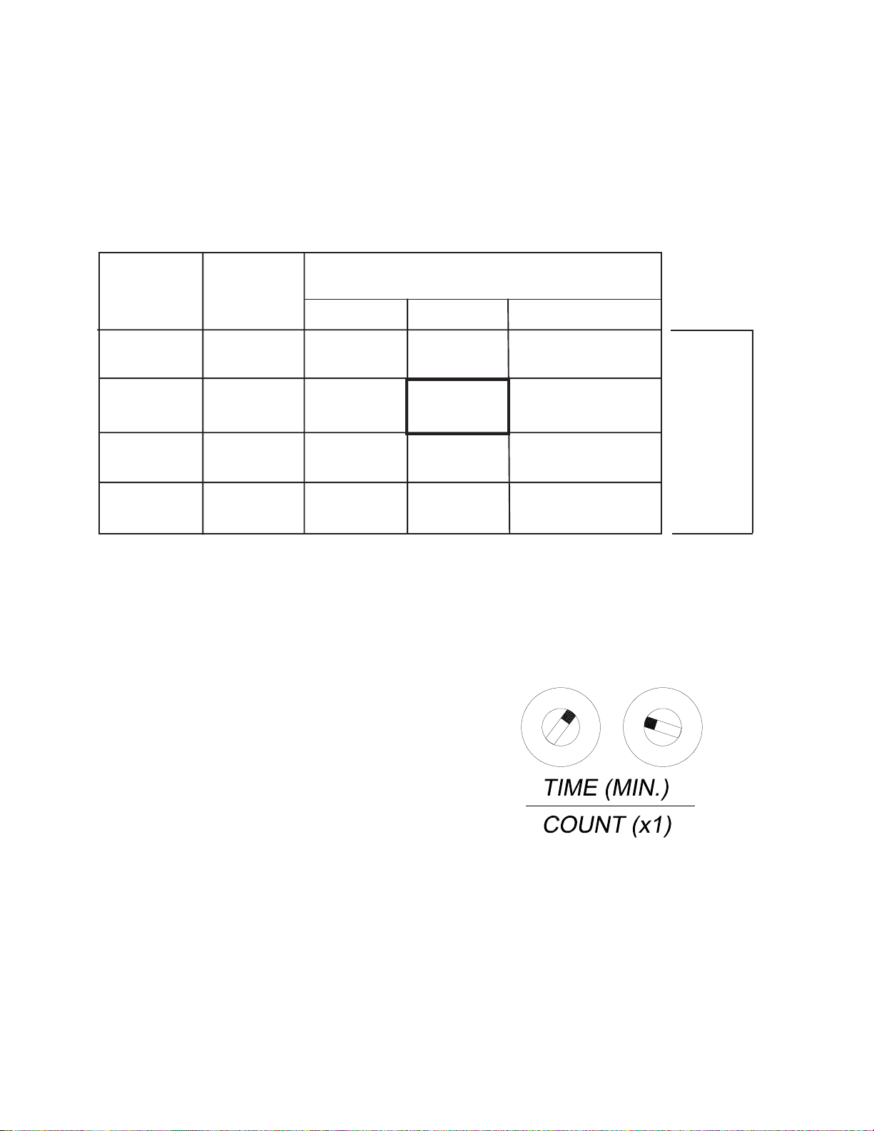
8.1 Calculate the sampling rate using the
following 30 day chart:
NOTE: To obtain maximum battery life, choose
the longest time interval and the largest pump
displacement setting possible.
18minutes
Example
8.2 Set the timer dials on the Z-65 to the sample
rate from step 8.1.
NOTE: The time (18 minutes) above corresponds
to the dial setting shown for the Z65 model with the
timer range setting in the factory position (jumper
on the two left pins). See section 12.4 Timer
Range Setting.
3
2
0
9
6
8
7
1
3
2
5
4
0
9
1
6
7
8
5
4
12 .400 18 36 60
913 27 45
3
6
4
918
915
30
.300
.200
.100
Numberofturns
openonpump
strokeknob
sample
pump
displacement
perstroke 1000 cc 500 cc 300 cc
Sample cylinder volumes
Sample
rate
(minutes)
8. Sampler Set-Up - Time-based sampling
Dieses Handbuch passt für folgende Modelle
1
Inhaltsverzeichnis
Andere YZ Systems Probennehmer Handbücher

YZ Systems
YZ Systems DynaPak Series Montageanleitung

YZ Systems
YZ Systems DynaPak DP-2010 Stücklistenhandbuch

YZ Systems
YZ Systems DynaPak DP-2010FU Stücklistenhandbuch

YZ Systems
YZ Systems DynaPak DP-2010JF Stücklistenhandbuch

YZ Systems
YZ Systems DynaPak DP-2010RXN Stücklistenhandbuch

YZ Systems
YZ Systems DynaPak DP-2010RN Stücklistenhandbuch

YZ Systems
YZ Systems DynaPak DP-2010UX Stücklistenhandbuch


