
Zubler Z1 ECO Bedienungsanleitung
Z1 ECO PRO
Z1 CAM PRO
Z1 PRO
EN 02-2020
Single suction systems
www.zubler.de

2
0. User information page 4
0.1 Declaration of conformity
0.2 Intended purpose of use
0.3 Technical requirements
1.
Installation of the appliance
page 6
1.1 Scope of supply and accessories
1.2
Installation of the extraction system
1.3 Connection of dust producers
1.3.1
Appliances without interfaces
1.3.2 Appliances with switching output
1.3.3 Appliances with switching output
with a 24 V interface or a 230 V socket
1.4 Intake system
2.
Functional description
page 16
2.1 Control unit
2.2 Commissioning
2.3 Automatic operation
2.4
Selecting and saving suction levels
2.5 Current suction power
2.6 Setting the suction overrun time
2.7
Fine tuning of the automatic operation
2.8
Switching the extraction system off
Content

3
3. Warranty terms page 22
3.1 Filter bag
3.2Main filter
3.3 Exhaust filter
3.4Motor
3.4.1 Motor replacement
3.4.2 Carbon brush replacement
4.5 Spare parts
3.6 Technical structure
4. Error Codes page 33
5. Technical Data page 36
6. Warranty
page 37
7.
Disposal instructions
page 38
Advanced settings are provided by the Zubler Sucti-
on-Technology APP , which is available for Android
tablets or phones.
Therefore follow the users manual of the Zubler Suc-
tion-Technology APP, which is downloadable from
www.zubler.de.

4
0.
0.1 Declaration of conformity
Introduction
Dear customer,
we are pleased, that you have decided for a Zubler extraction system and
hope it will enhance your work. The continuous development of our tech-
nology is based on the co-operation with experienced
dental technicians. The focus lies on the aim to optimize the extraction
technology in the fields of performance, noise and reliability.
Please read this operating manual carefully in order to ensure a prob-
lem-free operation.
We, Zubler Gerätebau GmbH
Buchbrunnenweg 26
89081 Ulm Jungingen
declare, that the product vacuuming unit
Z1 ECO PRO
Z1 CAM PRO
conforms to the health and safety
requirements set out in the directives
2014/30/EC EMV-Directive
2014/35/EC Low-Voltage Directive
2006/42/EC Machines Directive
2011/65/EU RoHS Directive
Any modification not specifically approved
by us voids the validity of this declaration.
Kurt Zubler
ceo

5
0.2 Intended purpose of use
0.3 Operating Environment
Temperature: +5°C bis +40°C
Max. permissible relative humidity: max. 80% (bei 30°C)
Total connected load : 10A
Compressed air, free of oil and moist min.5,0bar
This extraction system is designed exclusively for dry dusts!
Its use for the extraction of other types of dust or gases must be clarified
with the manufacturer before putting into operation.
Work must be stopped immediately and the system switched off in the
event of the appearance of visible clouds of dust or noticeably insufficient
suction power.
Inform your dealer or our service team.
The Z1 is designed for indoor use.
The volume of air circulated by the system and returned to the room may
not exceed 50% of the room air volume in closed rooms.
Use is restricted to persons who have been trained in its handling and are
authorised to do so. We reserve the right to make changes even without
updating this manual.
6
1. Installation of the appliance
1.1 Scope of supply and accessories
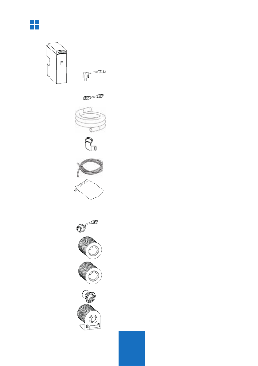
1x Z1 ECO/CAM PRO
extraction system
1x Power cable
1x
cable C13/C14 (ECOonly)
1.8m hose 38 mm
1x elbow adaptor 50/40 mm
compressed air hose (6mm)
dustbag with 20l
Special Accessories Item Number
Adaptor C14 / CEE
012-00702
H14-Filter H-Typ 556-0052
Activated carbon filter C-Typ
556-0051
exhaust adapter RD72 /DN75
896-1103
diffusor-holder (without Filter)
556-0057
7
16
1
3
2
2
30
1.2 Installation of the extraction system
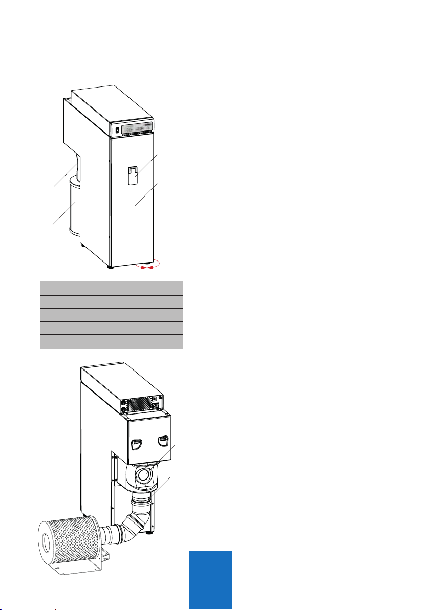
Fig. 1
Fig. 2
1.2.1 Suction line
nProvide a sufficiently stable and
leveled surface. Ensure that the
housing does not touch the furniture
to avoid noise production by
resonances.
nIf necessary the unit can be leveled by
turning the feet up/down (Fig.1).
nPlug in the muffle of the enclosed
suction hose to the intake nozzle (2)
and the other side firmly to your intake
system.
Use the enclosed 90° adaptor if
running sideways.
1 Closure
2 Exhaust connection
3 Filter door
16 Diffusor
30
Exhaust Adaptor
1.2.2 Exhaust
nIf using the unit in non-stop operation,
the exhausting air temperature is
increased.
nTo avoid overheating, the exhausting
air must be able to flow out and
spread free.
nIf this is not possible, the diffusor can
be removed and the exhausting air
can be guided with a DN75 hose or
pipe (Fig.2). Therefore use the optional
exhaust-adaptor RD72/DN75 O.No.
896/1103
nTo connect the diffusor to the DN75
hose or pipe you will need the optional
diffusor-holder O.No. 556/0057 (Fig.3)
nAlternatively it is recommended to
giude the exhaust air to the outside.
8
5
10
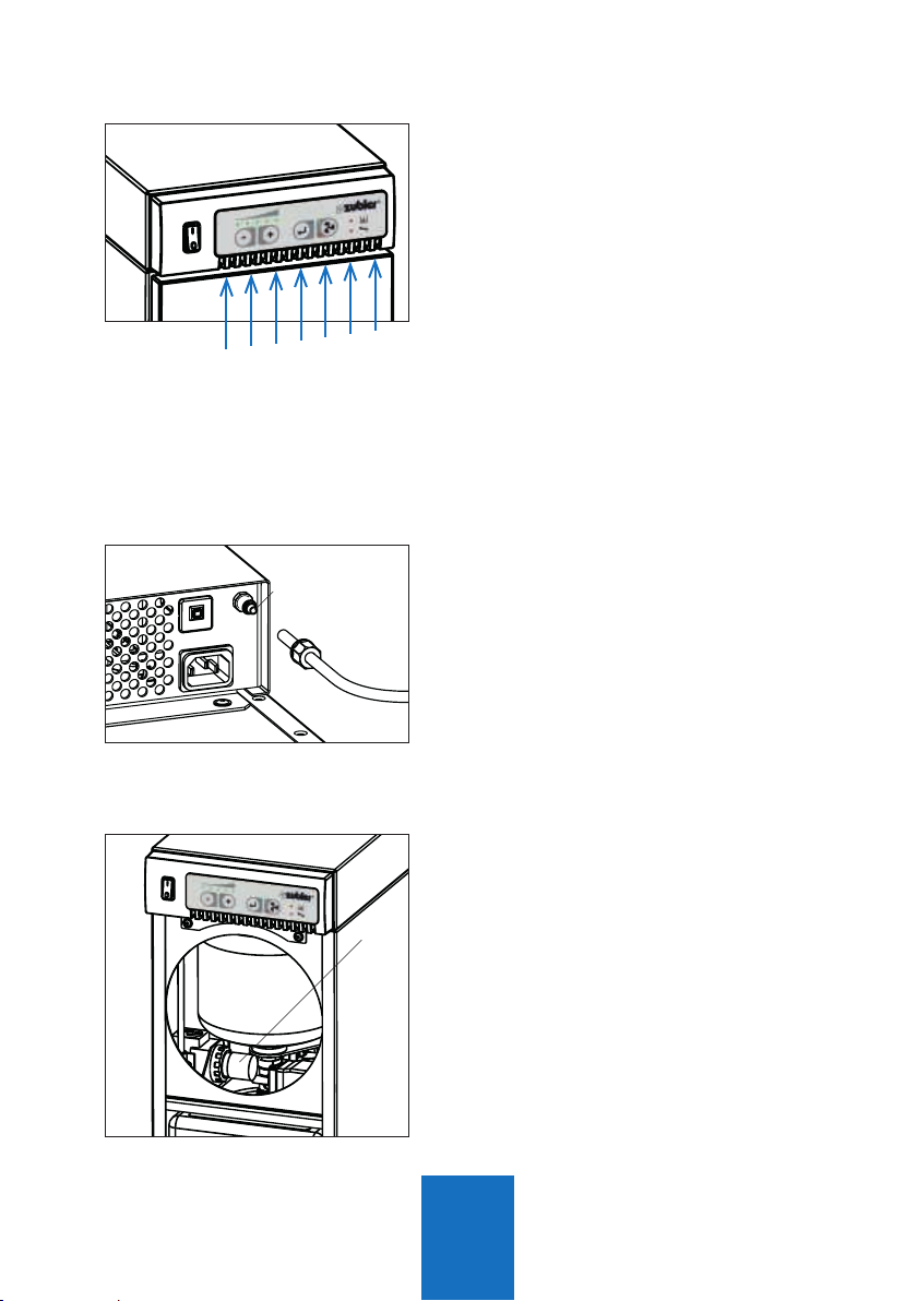
Fig. 3
Fig. 4
1.2.4 Compressed air
nThe suction unit Z1 PRO requires
compressed air for the filter cleaning.
The unit must not be used without
compressed air. Ensure there is a
compressed air supply available with
at min. 5 bar, free of oil and moisture.
nRemove the clamp screw of the
compressed air connector (5) and
insert the enclosed compressed air
hose (6mm). Plug the hose firmly
on the nozzle and tighten the clamp
screw. Connect the quick connector to
your compressed air supply.
nOpen the Frontdoor (Section 3.1, Fig.
14) and check if the pressure gauge
(10) on the pressure reducer shows
a pressure of 4-5 bar. The pressure
reducer is factory set and must not be
changed. Upon abnormal behaviour,
check your compressed air supply and
contact the Zubler Service.
1.2.3 Furniture integration
If integrating the suction unit into cabinets
or niches the following requirements
must be taken into account:
nThe suction unit must be able to draw
cooling air from the front (Fig.4)
nThe hot exhausting air which is
released on the back of the suction
unit, must not reach the front.
Therefore it is necessary, that there is
a tight barrier surrounding the suction
unit, separating the front from the
back. Alternatively it is also possible
to guide the exhausting air away from
the suction unit, see chapter 1.2.2.
Cooling air
Fig. 5

9
7.1
7.1
7.2
4
4
8
9
55
66
Fig. 7: Connectors CAM Fig. 8: Connectors ECO
1.2.5 Mains connection
nBefore connecting the unit to the
mains power supply, check if the
voltage given on the number plate
(Fig.6) corresponds with the local
voltage.
nPlug the enclosed power cord into the
IEC C14 connector 6 and the mains
plug into a local power socket.
nThe suction unit must not be switched
ON/OFF with the mains power supply.
The mains power supply must be
connected permanently.
4 Data interface
5 Compressed air connector
6
Mains power supply (IEC C14)
7.1
Main fuse (10A)
7.2
Fuse power socket (6A)
8
Autom. power socket (IEC F)
9 24V interface
ZUBLER Gerätebau GmbH
Buchbrunnenweg 26
D-89081 Ulm
Tel. +49(0)731 1452-0 / www.zubler.de
Absauganlage
Z1-ECO PRO
Spannung 230V
Gesamtleistung max. 2000W
Absaugung max. 700W
Automatiksteckdose 1200W
Z1 ECO PRO 00-11111-22
Made in
Germany
Fig. 6

10
3
2 4
1 5
6
1.3.1
Appliances without interface (ECO only)
n
If your appliance is equipped with a IEC
plug type C14, use the enclosed IEC
power cord (C13/C14) to connect the
appliance to power socket 8.
The power cord which was enclosed
with your appliance is not needed.
n
If your appliance is equipped with a CEE
mains plug type F or C, you will need an
optional CEE-adaptor (CEE/C14) O.No.
012/00701.
The max. power rate of the appli-
ance is limited to 600W (120V)or
1200W (240V)!
1.3.2 Appliances with switching output
nIf your working appliance has a
switching output, a control cable
(special accessory) can be used to
connect to the extraction system.
Instead of C13 low temperature power
outlet 8, use the data interface 4.
1.3 Connecting the working tools
Andere Handbücher für Z1 ECO
1
Dieses Handbuch passt für folgende Modelle
1
Inhaltsverzeichnis


