ZWAE MARK40 Handbuch

Installation and Service Manual
Zakład Wytwórczy Aparatów Elektrycznych Sp. z o.o.
MARK40
Vertical disconnector 123, 245 i 420 kV
Manual No. DTR.01.04.04.EN

Zakład Wytwórczy Aparatów Elektrycznych Sp. z o.o.
2
zwae.com.pl
WARNING!
During the operation of electrical equipment, certain parts of
these devices are normally under dangerous voltage, and me-
chanical parts, also remotely controlled, can move quickly.
Failure to follow the warning instructions can result in serious
personal injuries or material damage.
Only suitably qualied personnel can work on or near the device.
This personnel must know exactly all safety rules and rules for
maintaining the device in accordance with this instruction.
The problem-free and safe operation of this device requires
proper transport, proper storage, construction and assembly as
well as careful service and maintenance.

Zakład Wytwórczy Aparatów Elektrycznych Sp. z o.o.
3
Table of contents
1. TRANSPORT ...................................... 5
1.1. Unpacking and inspection ........................... 5
1.2. Storage and transport............................... 5
2. DESCRIPTION ...................................... 7
2.1. Construction and principle of operation ................ 7
2.2. Climatic conditions. . . . . . . . . . . . . . . . . . . . . . . . . . . . . . . . . 9
2.3. Nameplate ........................................ 9
2.4. Basic technical parameters .......................... 10
3. INSTALLATION AND ADJUSTMENT .................... 11
3.1. Preparation of contact surfaces ...................... 11
3.2. Assembling of the base frame........................ 12
3.3. Assembling of the insulators ......................... 13
3.4. Assembling of the movable contact head .............. 16
3.5. Assembling of the xed contact head with current path .. 16
3.6. Assembling of the corona ring of the knife ............. 17
3.7. Assembling of the corona rings of the movable
contact head of the knife ................................ 18
3.8. Assembling of the corona rings of the xed contact head. 18

Zakład Wytwórczy Aparatów Elektrycznych Sp. z o.o.
4
3.9. Assembling of the operating mechanism............... 19
3.10. Assembling of the driving shaft. . . . . . . . . . . . . . . . . . . . . . 19
3.11. Assembling of the xed contact of the earthing switch.. 20
3.12. Assembling and adjustment of the knife of the
earthing switch......................................... 21
3.13. Assembling of the earthing cable .................... 24
3.14. Table of tightening torque for screws [Nm] ............ 25
4. OPERATING MANUAL ............................... 25
4.1. Notes on switching operations....................... 25
5. INSPECTIONS AND MAINTENANCE .................... 26
5.1. Visual inspections ................................. 26
5.2. Periodic inspections................................ 26
5.3.Spare parts and recommended maintenance materials ... 26
6. UTILIZATION ....................................... 27
Zakład Wytwórczy Aparatów Elektrycznych Sp. z o.o.
5
1. TRANSPORT
1.1. Unpacking and inspection
Immediately after receiving the disconnector, the delivery’s compliance with the packing list should be chec-
ked. Then one should check whether the disconnector has not been mechanically damaged during transport
and the data on the nameplate match the order.
1.2. Storage and transport
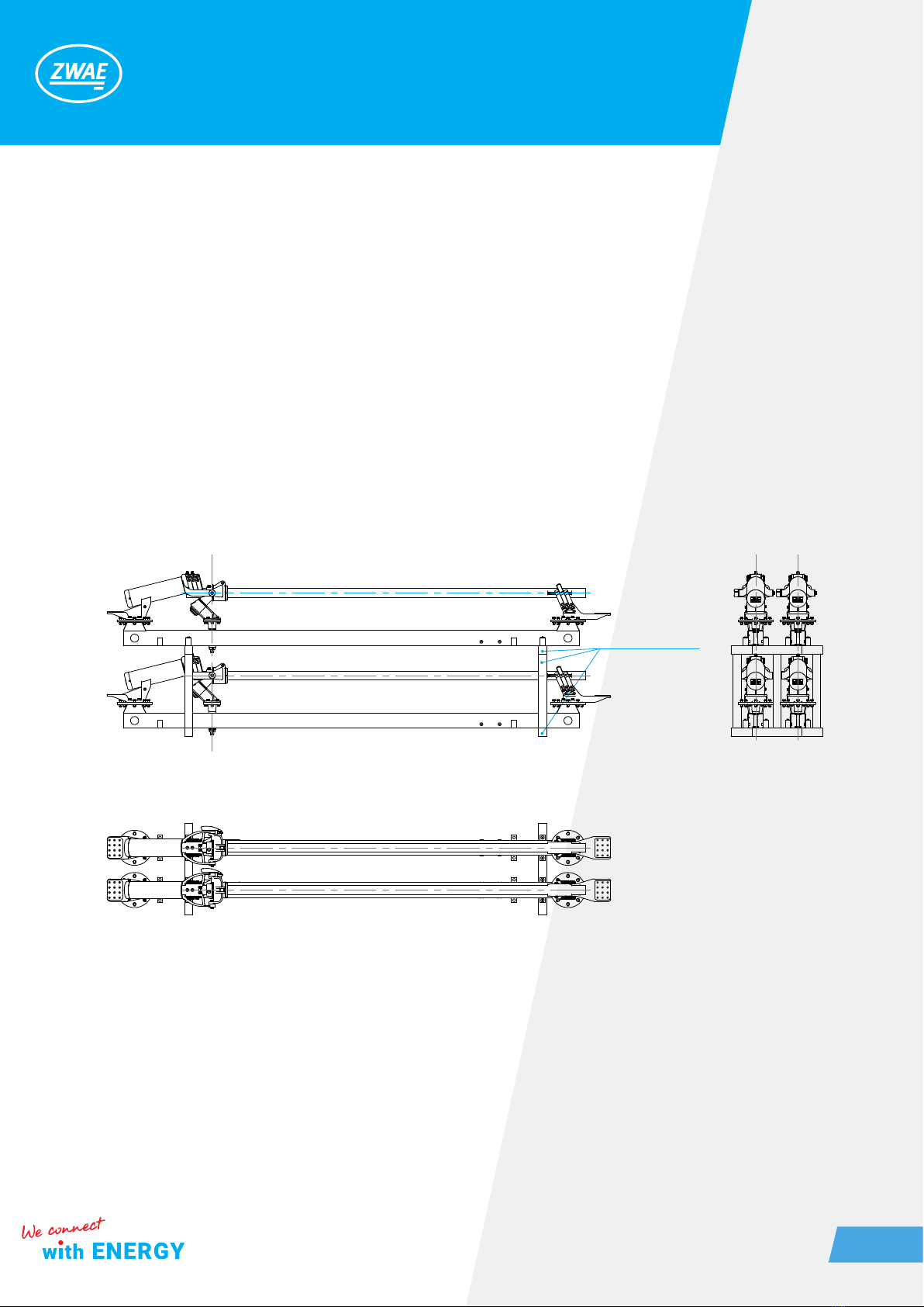
The disconnectors poles are transported in a partially assembled condition, ie the base frame together with
the current path form the basic set, while the other elements (insulators, contact’s corona rings, driving soc-
kets, etc.) are delivered separately for installing during assembly. The basic sets are packed in several pieces
on a wooden structure, as it is shown in the following drawing.
wooden structure
In the case of the purchase of a disconnector’s version with an earthing switch, all parts used for the earthing
switch’s construction ( the knife of earthing switch, counterweight beams, counterweights, pins, spacers, co-
upling tie rods, earthing switch contact, knife’s support and shaft of the earthing switch) are also delivered se-
parately in packs. When preparing the pole for assembly, the wooden beams should be removed by unscrewing
the four screws with the spanner 13.
Zakład Wytwórczy Aparatów Elektrycznych Sp. z o.o.
6
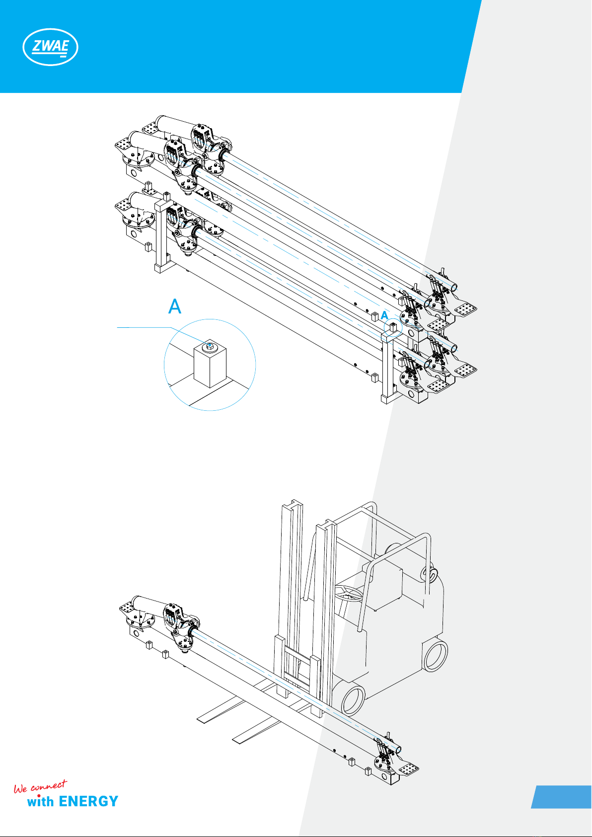
During unloading, the disconnector’s poles should be lifted with a forklift, as shown in the following graphics.
8x140 (4 pcs)

Zakład Wytwórczy Aparatów Elektrycznych Sp. z o.o.
7
During transportation, the poles must be secured against tipping over and the disconnector knife should be
closed. Disconnector can be transported by means of transport with open cargo area. Disconnectors poles
can be stored in an open space, but poles should be set so that the base frame does not stand directly on the
ground.
2. DESCRIPTION
2.1. Construction and principle of operation
The outdoor disconnector type Mark-40 is a three-column insulating switch with the secant movement of
contacts in the vertical plane, intended for work in networks with voltage depending on the version (123-420
kV) at frequencies up to and including 50 Hz. The disconnector can be used as a single-pole switch with an
individual operating mechanism. Disconnector’s poles can be set in parallel or in series. A visual sketch of
the Mark-40 disconnector pole with two earthing switches is presented below.
current path
supporting insulator
earthing switch (UN)
driving insulator
base frame
earthing switch (UR)
supporting structure
disconnector’s operating mechanism
earthing switch’s operating mechanism
Zakład Wytwórczy Aparatów Elektrycznych Sp. z o.o.
8
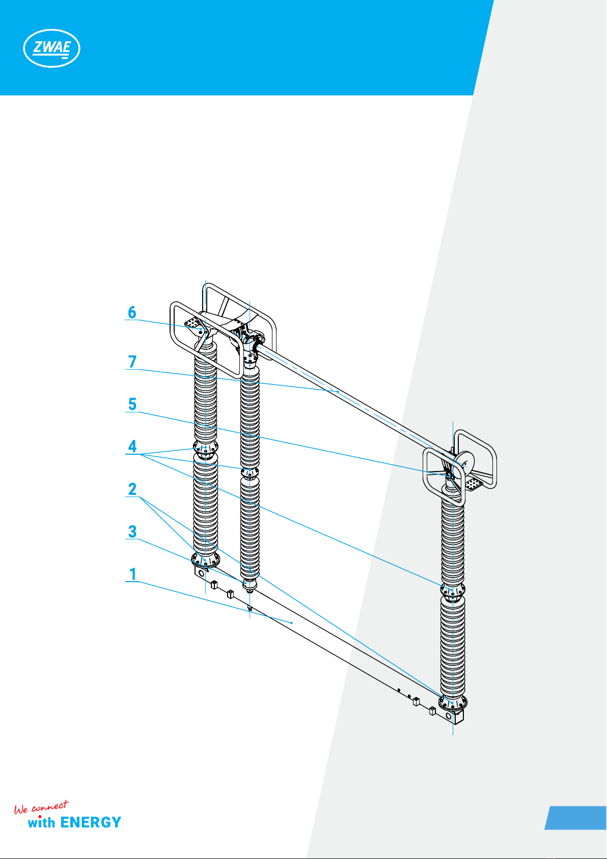
Details of the Mark-40 disconnector’s pole construction are illustrated in the next drawing. Each pole possess
an individual base frame [1] equipped with two xed feet [2] and a rotating foot [3] on which porcelain insulators
[4] are mounted. On top of the insulators are assembled the followings: movable contact head [5], xed contact
head [6] used to transfer the rotating movement of the driving insulator to the secant movement of current
path [7].

Zakład Wytwórczy Aparatów Elektrycznych Sp. z o.o.
9
2.2. Climatic conditions
The disconnector is adapted for outdoor operation, at ambient temperature from -40 to +40 ° C and relative
humidity up to 100%.
2.3. Nameplate
DISCONNECTING SWITCH
Rated voltage
weight
rated short-circuit withstand current (1sec.)
Lightning impulse withstand voltage
rated continuous current

Zakład Wytwórczy Aparatów Elektrycznych Sp. z o.o.
10
2.4. Basic technical parameters
No Parameter Value
1. Rated operating voltage 123 [kV] 245 [kV] 420 [kV]
2. Rated continuous current
2500 [A]
3150 [A]
4000 [A]
2500 [A]
3150 [A]
4000 [A
2500 [A]
3150 [A]
4000 [A]
3. Peak current 125 [kA] 125 [kA] 125 [kA]
4. Short-circuit current, 1 sec. 50 [kA] 50 [kA] 50 [kA]
5.
Test voltage (50 Hz):
- earth and pole to pole insulation
- contact to contact insulation
230 [kV]
265 [kV]
460 [kV]
530 [kV]
520 [kV]
610 [kV]
6.
Surge test voltage:
- earth and pole to pole insulation
- contact to contact insulation
550 [kV]
630 [kV]
1050 [kV]
1200 [kV]
1425 [kV]
1425 (+240)* [kV]
7.
Operational rated surge test voltage:
- earth insulation
- contact to contact insulation
-
-
-
-
1050 [kV]
900 (+345)* [kV]
8. Radio interference voltage <2500 [µV] <2500 [µV] <2500 [µV]
9. Mechanical strength 2000 cycles 2000 cycles 2000 cycles
10. Motor operating mechanism NSO80 NSO80 NSO80
* Peak values of alternating voltage supplied to the opposite terminal are shown in brackets
Inhaltsverzeichnis
Andere ZWAE Industrieanlagen Handbücher


