Alloy RNS5 Bedienungsanleitung

Alloy RNS5/8
Industrial 5-port/8-port Ethernet Rail Switch
User’s Manual
Rev.1.1
20-Jan-2005

Content
Introduction.........................................................1
Features...................................................................1
Package Checklist....................................................2
Hardware Description.........................................3
Dimensions ..............................................................3
Front Panel...............................................................3
Bottom View.............................................................5
Wiring the DC Power Inputs.....................................5
LED Indicators..........................................................6
Ports.........................................................................8
Cabling.....................................................................9
DIN-Rail Mounting.................................................. 10
Wall Mounting ........................................................12
Hardware Installation........................................13
Installation and Testing..........................................13

Introduction
Industrial environments are usually more demanding than office environments.
Harsh temperature conditions, vibration, dust, etc. all put higher demands on the
quality and reliability of your networking equipment. To survive harsh industrial
environments, Alloy provides you with the RNS5/8 Series Industrial 5-port/8-port
10/100Mbps Ethernet Switches. The RNS5/8 Industrial switch is a cost-effective
solution ideal for your industrial applications in harsh environments. The RNS5/8
not only gives you high speed data transmission over an Ethernet network, but
also provides redundant power inputs and reverse polarity protection. In addition,
the RNS5/8 is manufactured in an IP30 aluminum case, and has passed several
safety certifications, ensuring customers a cost-effective, safe, and reliable
industrial device.
Features
5-port /8-port 10/100T(X) industrial switch
Supports store-and-Forward switching architecture
Supports IEEE 802.3 10Base-T, 802.3u 100Base-TX standard
Supports auto MDI/MDI-X function
RNS5: 512 KB embedded memory
RNS8: 1024KB embedded memory
Supports IEEE 802.3x flow control
¾Flow control for full-duplex mode
¾Back pressure for half-duplex mode
Provides redundant dual power inputs
Aluminum case with IP30 protection
RNS5:1K MAC address table
RNS8:2K MAC address table
DIN-Rail and wall mountable design
1

Package Checklist
Alloy RNS5/8 Industrial 5-port/8-port Ethernet Rail Switches are packaged with the
following items:
RNS5/8 Industrial 5-port/8-port Ethernet Rail Switch
One DIN-Rail clip (attached to the RNS5/8)
One wall mounting plate and six screws
User’s manual CD-ROM
RNS5/8 Switch User’s Manual CD-ROM
WallMountingPlate Screws DIN-RailClip
Contact your sales representative if any item is missing or damaged.
2

Hardware Description
Dimensions
RNS5/8 Industrial 5-port/8-port Ethernet Rail Switch dimensions (W x H x D) are
54mm x 135mm x 105mm
FrontPanel
The Front Panel of the RNS5 Industrial 5-port Ethernet Rail Switch is shown in
Figure A.
LED Indicators
UTP Ports
Figure A. Front Panel of the RNS5 Industrial 5-port Ethernet Rail Switch
3

The Front Panel of the RNS8 Industrial 8-port Ethernet Rail Switch is shown in
Figure A.
LED Indicators
UTP Ports
Figure A. Front Panel of the RNS8 Industrial 8-port Ethernet Rail Switch
4

Bottom View
The bottom view of the RNS5/8 Industrial 5-port/8-port Ethernet Rail Switch
consists of one terminal block connector with two DC power inputs, Alarm output
and one DC IN power jack for an additional AC/DC power adapter.
Figure B. Bottom view of the RNS5/8 Industrial 5-port/8-port Ethernet Rail Switch
Wiring the DC Power Inputs
Follow the steps below to wire RNS5/8 dual DC power inputs.
[Note] The suitable electric wire ranges from 12 to 24 AWG.
V- V+V- V+
1. Insert the positive and negative wires into the V+ and V-
contacts respectively of the terminal block connector
2. Tighten the wire-clamp screws to prevent the DC wires
from being loosened.
5
[Note] The additional power jack is designed for office use.

LEDIndicators
There are 5 diagnostic LEDs and 8 Port LEDs located on the Front panel of the
RNS5 Industrial Ethernet Rail Switch. These LED indicators provide
administrators with real-time system status. Table 1 gives descriptions of the
functions of each LED indicator.
LED Status Description
Green Power is on.
PWR Off No power is being supplied.
Green Power is on.
PWR 1 Off No power is being supplied.
Green Power is on.
PWR 2
Off No power is being supplied.
Green A network device is detected.
Blinks The port is transmitting or receiving
packets from the TX device.
LNK/ACT of Port 5
Off No device is attached.
Orange The port is operating in full-duplex
mode.
Blinks Collision of packets occurs.
FDX/COL of Port 5
Off The port is in half-duplex mode or
no device is attached.
6
Port LED Status Description
Orange The port is operating in full-duplex
mode.
Blinking
orange Collision of Packets occurring.
Off The port is in half-duplex mode or
no device is attached.
Green A network device is detected.
Blinking
green
The port is transmitting or receiving
packets from the TX device.
Port Status (Port 1
to Port 4)
Off No device is attached.
Table 1
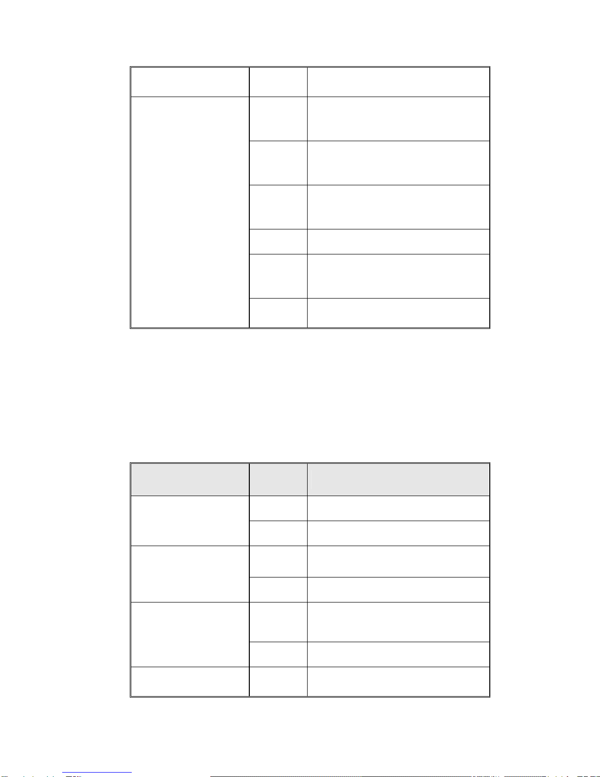
There are 7 diagnostic LEDs and 12 Port LEDs located on the Front panel of
RNS8 Industrial Ethernet Rail Switch. These LED indicators provide
administrators with real-time system status. Table 2 gives descriptions of the
function of each LED indicator.
LED Status Description
Green Power is on.
PWR Off No power is being supplied.
Green Power is on.
PWR 1 Off No power is being supplied.
Green Power is on.
PWR 2
Off No power is being supplied.
LNK/ACT of Port 7/8 Green A network device is detected.
7

Blinks The port is transmitting or receiving
packets from the TX device.
Off No device is attached.
Orange The port is operating in full-duplex
mode.
Blinks Collision of packets occurs.
FDX/COL of Port 7/8
Off The port is in half-duplex mode or
no device is attached.
Port LED Status Description
Orange The port is operating in full-duplex
mode.
Blinking
orange Collision of Packets occurring.
Off The port is in half-duplex mode or
no device is attached.
Green A network device is detected.
Blinking
green
The port is transmitting or receiving
packets from the TX device.
Port Status (Port 1
to Port 6)
Off No device is attached.
Table 2
Ports
RJ-45 ports (Auto MDI/MDIX): RNS5 has five 10/100 Mbps auto-sensing ports
for 10Base-T or 100Base-TX device connection. The UTP ports will auto-detect
10Base-T and 100Base-TX connections. Auto MDI/MDIX allows users to connect
another switch or workstation without changing straight through or crossover
cabling. See Figure C and C-1 for the schematic diagram of straight through and
crossover cabling.
8
Dieses Handbuch passt für folgende Modelle
1
Inhaltsverzeichnis
Andere Alloy Netzwerk-Router Handbücher


Beliebte Netzwerk-Router Handbücher anderer Marken


NETGEAR
NETGEAR FS526T - Switch Bedienungsanleitung

Korenix
Korenix JetNet 5710G Series Bedienungsanleitung

Automated Logic
Automated Logic ZN551 Betriebsanleitung

Cisco
Cisco ASR 1000 Series Bedienerhandbuch

EnGenius
EnGenius ESR-9710 Bedienungsanleitung

Cisco
Cisco 805 Series Bedienungs- und Sicherheitshinweise