
Amphony 1600 Handbuch

R
User and Installation Guide
Guide d’Utilisateur et d’Installation
5.8 GHz DIGITAL
Wireless Speaker Kit
5.8 GHz NUMÉRIQUE
Amplificateurs Sans Fil
Model 1600 / Modèle 1600

EN - Contents
Unpacking
Connecting the transmitter
Connecting the amplifiers
Placing the transmitter and amplifiers
Operating the transmitter
Operating the amplifiers
Troubleshooting
Technical specifications
Safety information
Your warranty
FR - Table des matières
Déballage
Branchement du transmetteur
Branchement des Amplificateurs
Emplacement du transmetteur et des amplificateurs
Fonctionnement du transmetteur
Fonctionnement des amplificateurs
Tableau de problèmes/solutions
Spécifications technique
Instructions de Sécurité
Garantie Limitée
....................................................................................... 2
.............................................................. 2
............................................................... 4
............................................. 5
................................................................ 6
................................................................. 7
.............................................................................. 8
................................................................ 10
......................................................................... 11
................................................................................ 12
...................................................................................... 13
...................................................... 13
.................................................. 15
.................... 16
.................................................. 17
.............................................. 18
................................................... 19
............................................................... 21
................................................................ 22
........................................................................... 23
Copyright (C) 2010 Amphony. All rights reserved.
The information contained herein is subject to change without notice.
Revisions may be issued to advise of such changes and/or additions.
All product names, trade names, or corporate names mentioned in this
document are acknowledged to be the proprietary property of the registered
owners.
FCC ID PMJT1500
This device complies with part 15 of the FCC Rules. Operation is subjected
to the following two conditions: 1) This device may not cause harmful
interference and 2) this device must accept any interference received,
including interference that may cause undesired operation.
Caution: Any changes or modifications not expressly approved by the party
responsible for compliance could void the user's authority to operate the
equipment.
User and Installation Guide
R
Step1
Connecting the transmitter
The transmitter connects either to a standard line-out audio interface via the
supplied RCA cable or to an amplified speaker output via the supplied short
speaker cables.
If the transmitter is connected via speaker cables, observe the polarity of the
cable connection to ensure that the transmitter will be fed with a correct
polarity signal. If one of the cables is switched (reversed), one speaker will
receive an opposite polarity signal which will degrade sound performance.
The transmitter can also be connected to other audio outputs by using an
appropriate adapter.
Connect the supplied small AC adapter’s barrel-shaped plug into the DC 9V
jack, and then plug the transformer into a standard AC outlet. We recommend
the use of a surge protector to protect the transmitter from power surges.
Unpacking: Check that this package contains:
One 5.8 GHz Digital Audio transmitter - Model 1550, two 5.8 GHz Digital Audio
amplifiers - Model 1550, one small and two large AC adapters (wallwarts), four
short speaker cables, one RCA audio cable.
ATTENTION! Do not use both the speaker cables and RCA cable. Do not connect
speakers to the transmitter. Do not connect the large AC adapter to
the transmitter.

User and Installation Guide
R
LRDC 9V
L R
DC 9 V
250 mA
Power outlet
AC adapter
Page 3
Using the transmitter RCA audio input:
Using the transmitter speaker audio input:
L R
SPEAKER OUT
Audio Source
Transmitter
LRDC 9V
L R
L R
AUDIO
LINE OUT
Audio Source
Transmitter
DC 9 V
250 mA
Power outlet
AC adapter

User and Installation Guide
R
Step2
Connecting the amplifiers
ATTENTION! Never short circuit any amplifier audio output since this may
damage the amplifier. A clicking noise may be generated during
amplifier power up. Therefore, it is recommended to connect power
to the amplifier prior to connecting the speakers.
Page 4
Amplifier for left speaker
DC 36 V
Power outlet
AC adapter
Left speaker
Connect the DC power input of the amplifier with the supplied large 24 V AC
adapter (wallwart). ATTENTION: Connect the amplifier to the AC adapter
BEFORE connecting the AC adapter to the power outlet to avoid sparks due to
rush-in current.
Each amplifier connects to regular passive loudspeakers via the supplied speaker
cable. Observe the correct polarity when connecting the speakers.
Connect the left speaker to the amplifier marked “LEFT”. Connect the right
speaker to the amplifier marked “RIGHT”.
Connect the right speaker to the amplifier for the right speaker similarly.
Speaker connections:
Model 1600
DC 36V
User and Installation Guide
Page 5
R
Step3
Placing the transmitter and amplifiers
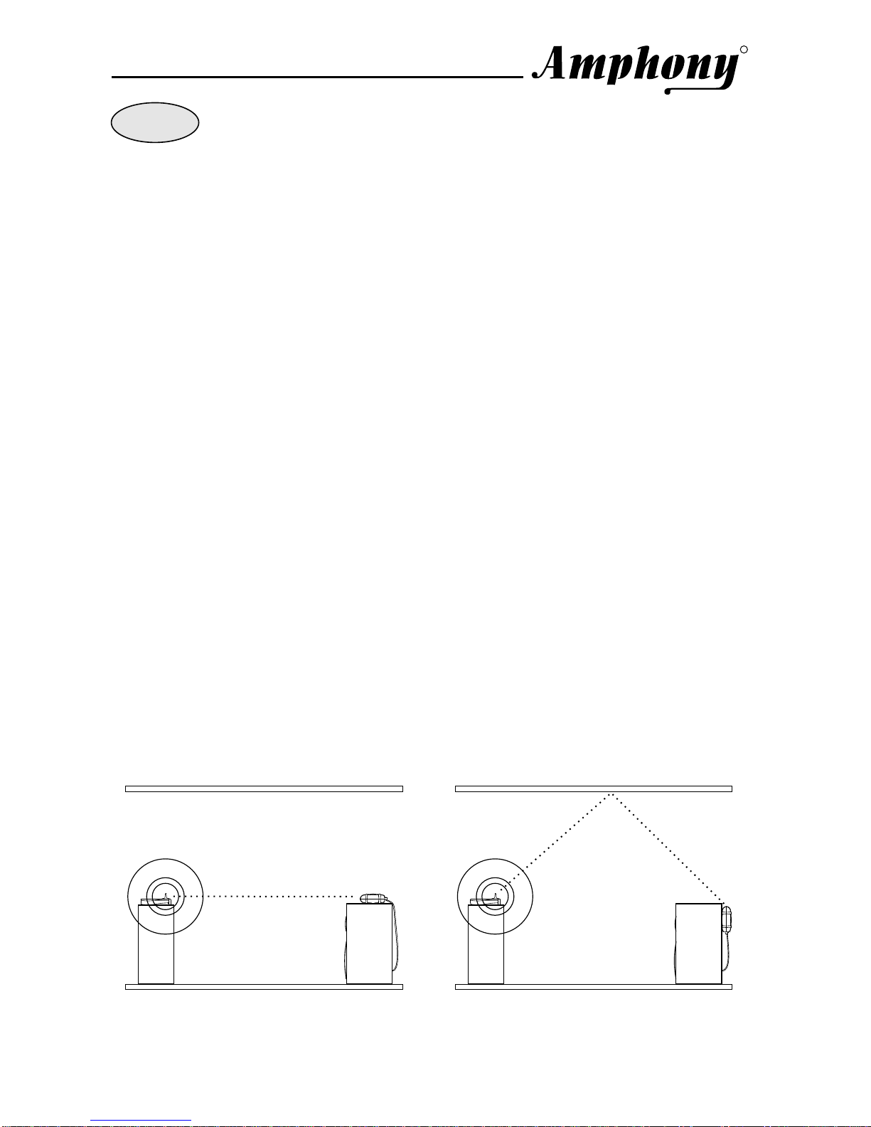
For best reception, we recommend that each amplifier be placed within the line
of sight from the transmitter. If possible, each amplifier should be placed right
side up with its front toward the transmitter.
The transmitter should be placed at an elevation such that there are no
obstacles between the transmitter and amplifiers (line of sight) in an area where
there will be the least amount of traffic. We suggest that you place the
transmitter on top of your audio source. Example 1 below shows the optimum
placement of the transmitter and an amplifier. If no line of sight is possible, place
the transmitter and amplifiers such that there is the minimum possible number of
walls and obstacles between the transmitter and each amplifier.
The amplifiers can also be placed as shown in example 2. In this case, no line-
of-sight connection exists and the operating range is reduced.
You can mount the amplifiers vertically by using the 2 screw openings at the
bottom of each amplifier. If the amplifiers are mounted vertically, the operating
range is reduced compared to mounting the amplifiers right side up.
Each amplifier incorporates a directional antenna which prefers signals
transmitted toward the front of the amplifier. Therefore, the front of the amplifiers
should always be facing toward the direction of the strongest transmitter signal.
By properly orienting each amplifier, interference from other signal sources can
be minimized.
We suggest that you experiment with placement in order to find the best location
for the transmitter and amplifiers.
Note: This product will not work properly from within an enclosed metal cabinet.
Example 1: Amplifier placed
on top of a speaker Example 2: Amplifier mounted
vertically behind a speaker
Transmitter
Speaker
Amplifier
Transmitter
Speaker
Amplifier
line of sight indirect connection
(reflected signal)

Step4
Operating the transmitter
After powering up the transmitter, the transmit light will go on for approximately
five seconds while the transmitter initializes.
After initialization, the transmit light will go out.
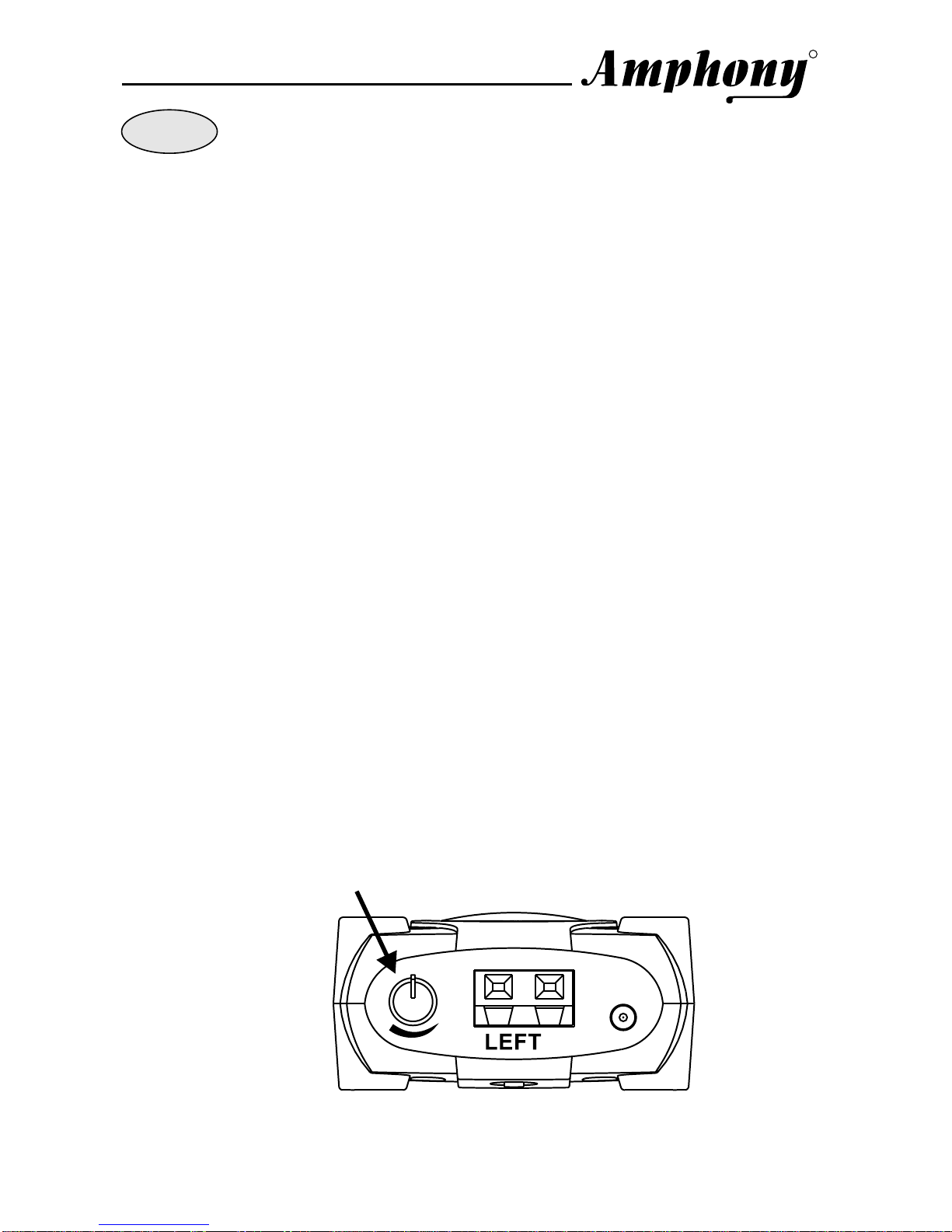
Initially, set the transmitter volume control to a middle setting.
Once audio is detected at the audio input, the transmit light will go on and the
transmitter will transmit the audio signal.
When audio is no longer detected, the transmitter will go into standby mode
after approximately one minute. The transmit light will go out. During standby
mode, no signal is transmitted.
5.8 GHz Digital Audio Transmitter
R
TRANSMIT
Transmit light
User and Installation Guide
Page 6
R
Transmitter volume control
LRDC 9V
L R
User and Installation Guide
Page 7
R
Step5
Operating the amplifiers
As soon as a valid transmitter signal is received by the amplifiers, the amplifiers
will output the amplified audio signal to the speaker outputs. The amplfier marked
“LEFT” will output the left audio channel and the amplifier marked “RIGHT” will
output the right channel. You can change the audio level by adjusting each
amplifier volume control.
If no audio signal is received for more than 2 minutes, the amplifiers will go into
standby mode (power-down mode).
In order to achieve maximum transmission quality, the transmitter volume control
should be set to match the audio level of your audio source as follows:
1) Set the amplifier volume control to a low level to prevent clipping inside the
amplifiers.
2) Set your audio source to output the maximum audio level that you will
encounter during normal operation such that both the left and right channel are
balanced.
3) Turn the transmitter level control knob to the position that yields maximum
audio loudness to the speakers without any clipping (distortion). If the
transmitter level is set too low, the dynamics of the transmission are not fully
used. If the level is set too high, audio clipping (distortion) will occur inside
the transmitter.
4) Turn each amplifier volume control to a setting that yields the desired volume
from the speakers such that the volume at both speakers is balanced.
Amplifier volume control
Model 1600
DC 36V
User and Installation Guide
Page 8
R
Troubleshooting
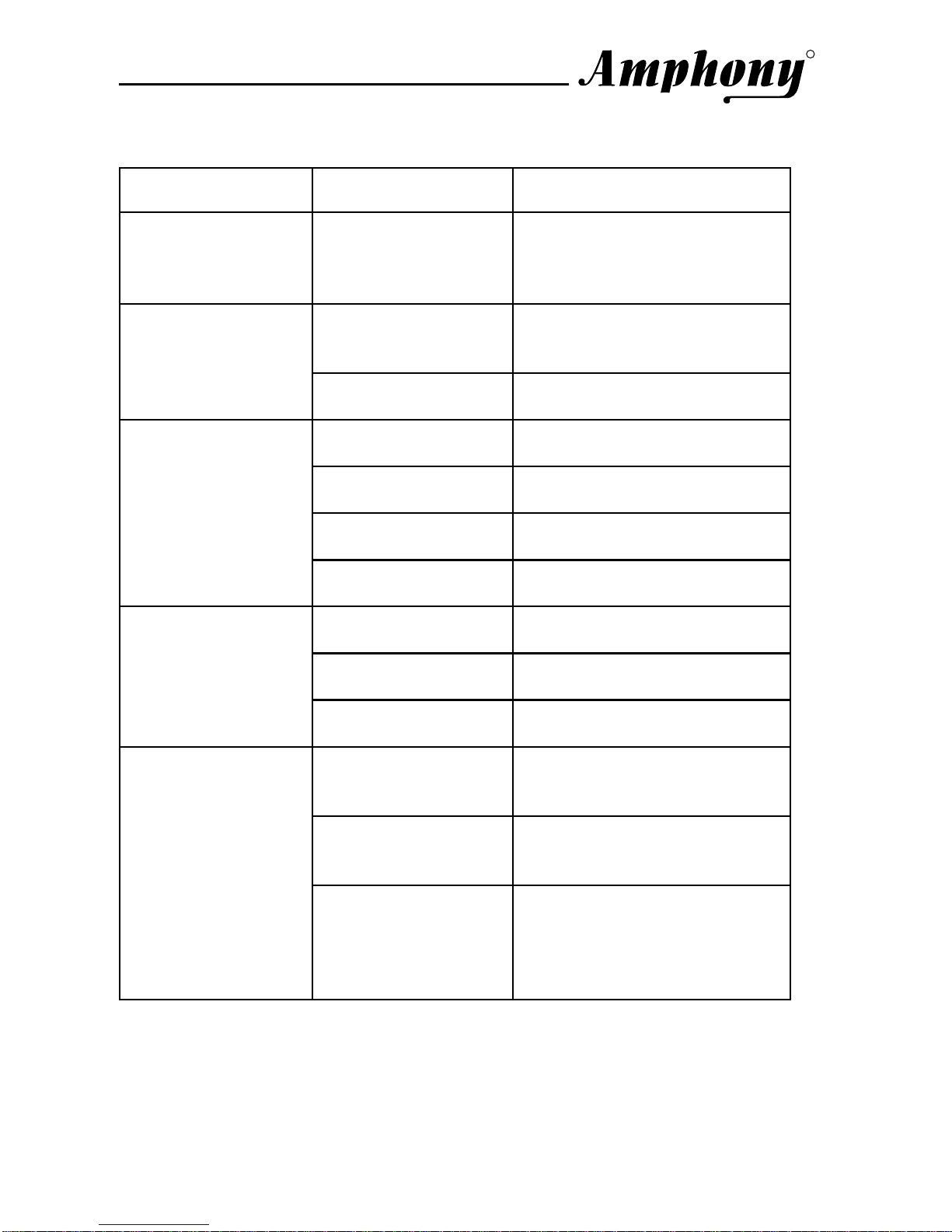
Problem Possible Cause Solution
The transmit light
does not go on after
DC power is applied
to the transmitter
Faulty AC adapter
or faulty power outlet Check the power outlet and
the AC adapter; if possible,
check for correct voltage of
the AC adapter.
No audio present at
audio input Check the audio connection
to the transmitter and ensure
that there is audio present.
The transmit light
goes out after a few
seconds and does
not light again Transmitter hung up Disconnect and then
reconnect DC power.
Faulty AC adapter
or faulty power outlet See under “Faulty AC adapter
or faulty power outlet“ above.
Transmitter volume
control set too low Adjust the transmitter volume
control.
Amplifier volume
control set too low Adjust the amplifier volume
control.
No audio at
amplifier
Strong interference See under “Strong
Interference“ on next page.
Transmitter volume
control set too high Adjust the transmitter volume
control until clipping stops.
Amplifier volume
control set too high Adjust the amplifier volume
control until clipping stops.
Audio is distorted
Strong interference See under “Strong
Interference“ on next page.
Transmitter volume
control set too low Adjust the transmitter volume
control to achieve desired
audio level.
Amplifier volume
control set too low Adjust the amplifier volume
control to achieve desired
audio level.
Speaker audio level
is too low
Audio signal too
weak Increase the output level of
the audio source (connect
transmitter to an adjustable
output by using an adapter if
necessary).

User and Installation Guide
Page 9
R
For more information, including a detailed troubleshooting guide,
visit the Amphony web site at: www.amphony.com
Problem Possible Cause Solution
Strong interference In some cases, there may be
strong interference preventing
proper reception of the audio
signal which can be caused
by 5.8 GHz cordless
telephones or 5.8 GHz
wireless networks. Either
eliminate the interference,
locate the base unit of the
cordless phone in another
room, set the wireless
network to use the 5.1 GHz
frequency band rather than
5.8 GHz, relocate the
transmitter, relocate or
reorient the amplifier to
improve reception.
Audio drops out
intermittently or
crackles
Unstable power
supply Ensure that the power outlet
delivers a stable voltage. Very
strong surges or voltage
fluctuations may cause audio
dropouts. Try using a surge
protector.
Strong interference See under “Strong
Interference“ above.
Transmitter volume
control set too low Adjust the transmitter volume
control.
Audio is noisy
Audio signal too
weak See under “Audio signal too
weak“ on previous page.
Strong interference See under “Strong
Interference“ above.
Transmitter range is
extremely short Too many obstacles Audio will drop out if there are
too many obstacles between
the transmitter and the
amplifier (see page 4), try
relocating the amplifier or
transmitter to improve
reception.
Andere Handbücher für 1600
1
Dieses Handbuch passt für folgende Modelle
2
Inhaltsverzeichnis
Sprachen:
Andere Amphony Sprecher Handbücher

Beliebte Sprecher Handbücher anderer Marken


Bowers & Wilkins
Bowers & Wilkins 4 Bedienungsanleitung

Sonance
Sonance SONOS OUTDOOR Series Bedienungsanleitung

Electro-Voice
Electro-Voice EVID FM4.2 Bedienungsanleitung

Pioneer
Pioneer XW-HTD630 Bedienungsanleitung

Onn
Onn BWA16AA002 Bedienungsanleitung

HP
HP GL313AA - USB Speakers PC Multimedia Bedienungsanleitung