
AVK 29 Series Gebrauchsanweisung

AVK SERIES 29 HYDRANT
INSTALLATION, OPERATION & MAINTENANCE MANUAL
Instruction for use
Thank you for selecting an AVK product. With correct use, the product is guaranteed to deliver a long and
reliable service. This manual has been prepared to assist you with the installation, operation and maintenance
of the hydrant to the maximum efficiency. For ease of reference, it has been divided into sections covering all
aspects of use, and it is in the users best interests to read it and ensure that it is fully understood.
Health and Safety
It is always recommended that wherever work is being carried out on a valve that the valve is fully
depressurised prior to carrying it out, and for the convenience draining of the line may be beneficial.
It is essential that the user of the valve is aware of the weight of the components and/or assembles that must
be handled and manipulated during installation and maintenance. It is the users responsibility to ensure that
safe working practices are followed at all times.
Whenever AVK products are installed, operated, or maintained, it is essential that the staff that undertake
these operations be adequately trained. The hazards of pressurised liquids and gases can be severe, and it
is the responsibility of the users to ensure that trained, competent staff undertake these duties. This manual
has been designed to assist, but it can never fully replace quality training in the workplace. AVK technical staff
will always be available to answer any questions relating to specific problems that may not be covered by this
manual.
AVK products are designed and manufactured to be fit for purpose, and to a high and reliable standard. This
provides a safe product with minimum risk to health when used correctly for the purpose for which it was
designed. However, this assumes that the equipment is used and maintained in accordance with the manual,
and the user is advised to study this manual, and to make it available to all staff that may need to refer to it.
AVK cannot be held responsible for any incidents arising from incorrect installation, operation or maintenance.
The responsibility for this must rest wholly with the user.
AVK Valves Pty Ltd, 559A Grand Junction Road, Wingfield, SA 5013, Australia - T: +61 8 8368 0900 - E: [email protected] - W: www.avkcivil.com.au Version number 3
COPYRIGHT©AVK GROUP A/S 2017 pp. 1 of 6
AVK SERIES 29 HYDRANT
INSTALLATION, OPERATION & MAINTENANCE MANUAL
1. Introduction
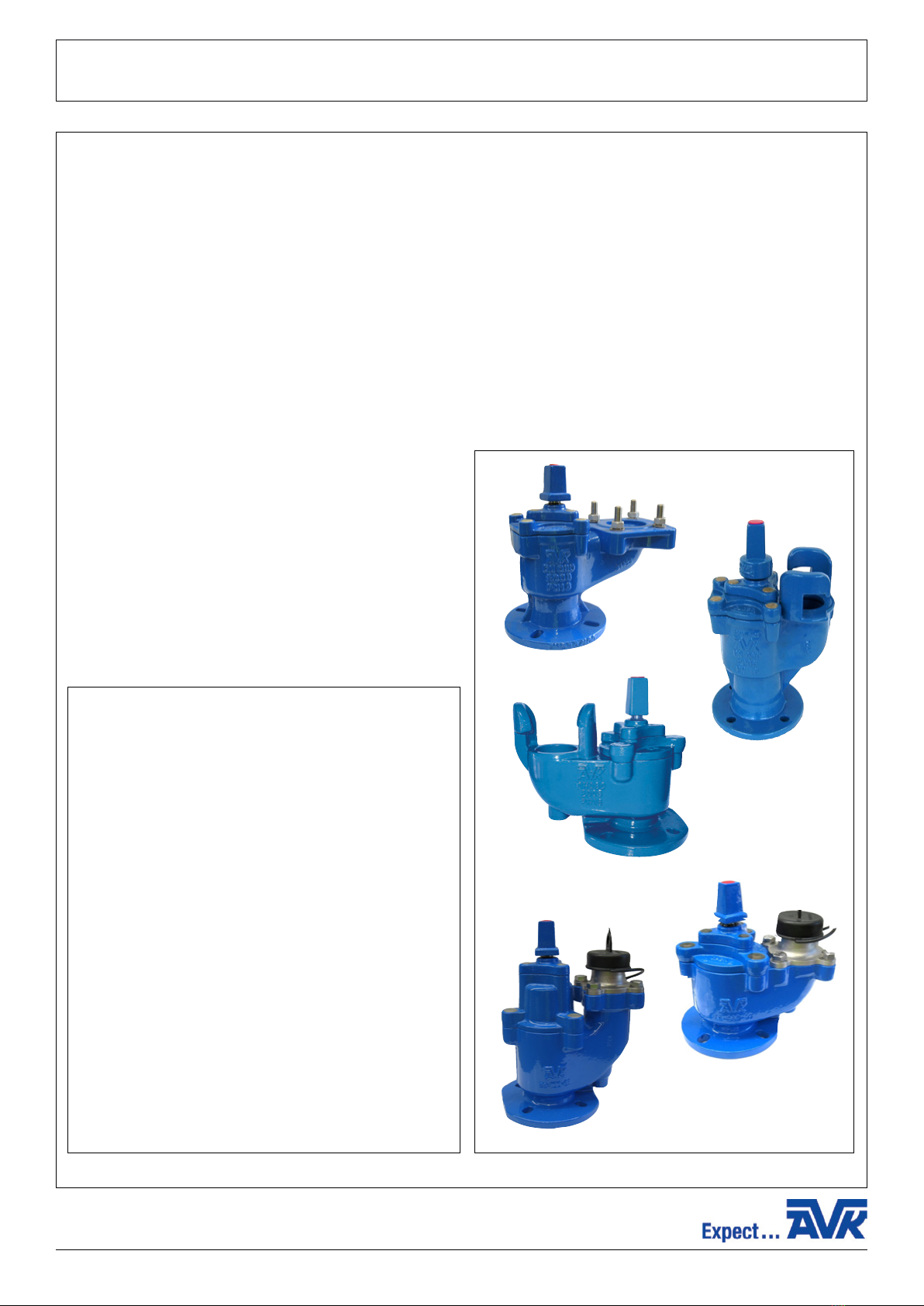
AVK series 29 hydrants are designed to meet local specifications and include:
SA Hydrant - Series 29/010
WA Hydrant - Series 29/088
NT Hydrant - Series 29/288
NZ Squat with 2" round thread outlet - Series 29/588
NZ Tall with 2" round thread outlet - Series 29/589
Hydrant Isolation Valve - Series 29/00
AVK series 29 hydrant valves have DN80 bore.
The valves are 100% factory tested hydrostatically.
IT IS IMPORTANT TO STATE OPERATING TEMPERATURE, PRESSURE, MEDIUM AND OPERATING CONDITIONS WITH
ENQUIRIES/ORDERS, SO THE MOST SUITABLE VALVE WILL BE SUPPLIED FOR YOUR SPECIFIC PURPOSE.
AVK Valves Pty Ltd, 559A Grand Junction Road, Wingfield, SA 5013, Australia - T: +61 8 8368 0900 - E: [email protected] - W: www.avkcivil.com.au Version number 3
COPYRIGHT©AVK GROUP A/S 2017 pp. 1 of 6
AVK Valves Pty Ltd, 559A Grand Junction Road, Wingfield, SA 5013, Australia - T: +61 8 8368 0900 - E: [email protected] - W: www.avkcivil.com.au Version number 3
COPYRIGHT©AVK GROUP A/S 2017 pp. 2 of 6
Materials:
Castings (body, bonnet, stem cap, stopper & gland
flange)
Ductile Iron to AS 1831 Grade 500-7
Coating
Fusion bonded epoxy (FBE)
Stem, isolation valve studs, nuts & washers
Stainless Steel
O-rings
NBR rubber
Stopper rubber
EPDM rubber
Bolts
Grade 8.8 encapsulated with hot melt glue
Thrust collar, stopper nut
Dezincification resistant brass CZ 132 to BS 2872
Screwed outlet
Stainless steel with 316 bolts
Dust cap
PE for screwed outlet
Refer to individual datasheets for specific information
29/00
29/010
29/088
29/288
29/588
AVK SERIES 29 HYDRANT
INSTALLATION, OPERATION & MAINTENANCE MANUAL
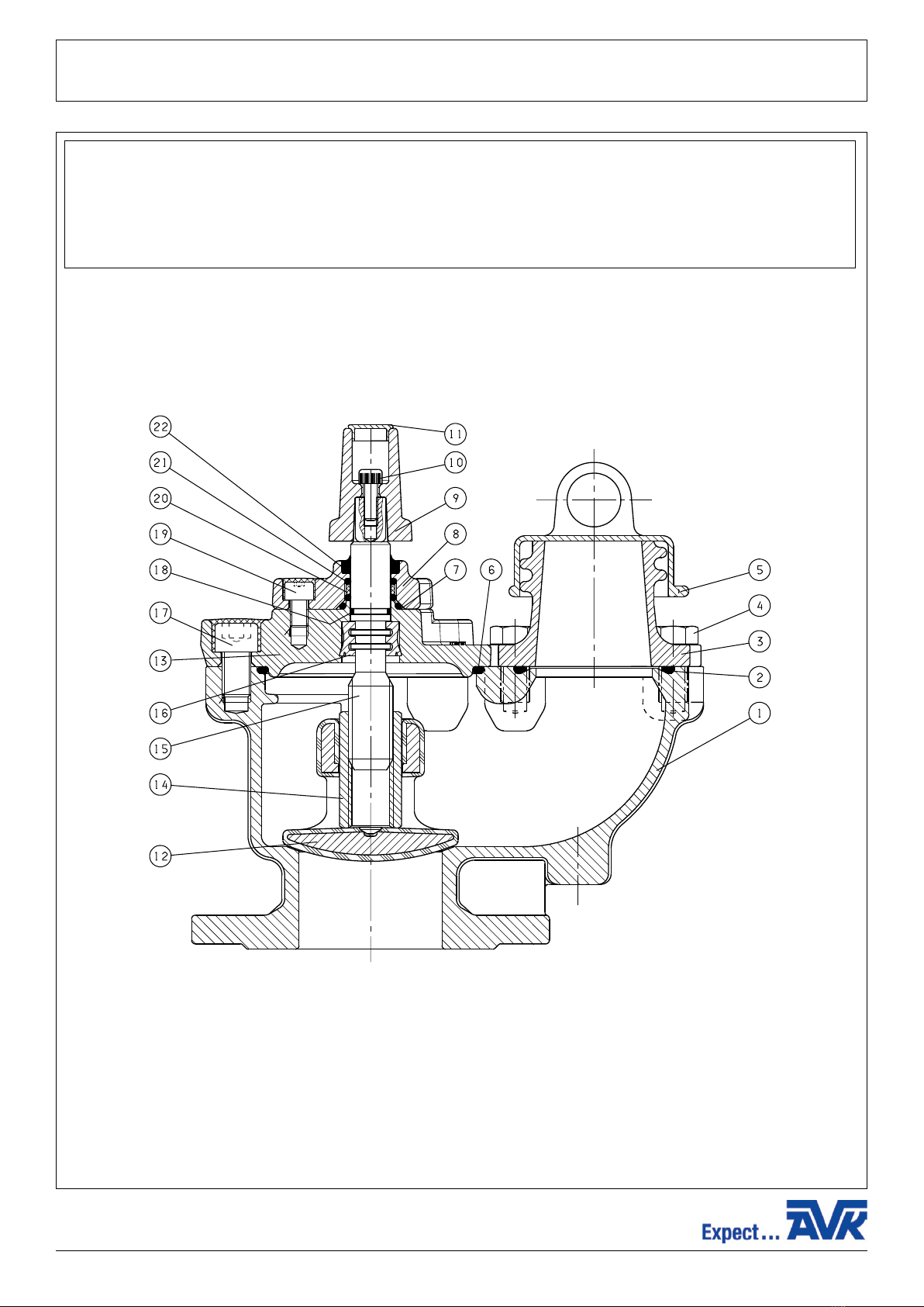
Component list
1. Body squat
2. Outlet O-ring
3. Outlet
4. Outlet bolt
5. Dust cap
6. Bonnet O-ring
7. Gland O-ring
8. Gland flange
9. Stem cap
10. Cap bolt
11. Insert
12. Stopper
13. Bonnet
14. Nut for loose stopper
15. Stem
16. Thrust collar
17. Socket head screw
18. O-ring
19. Socket head screw
20. Bush
21. O-ring
22. Wiper ring
AVK Valves Pty Ltd, 559A Grand Junction Road, Wingfield, SA 5013, Australia - T: +61 8 8368 0900 - E: [email protected] - W: www.avkcivil.com.au Version number 3
COPYRIGHT©AVK GROUP A/S 2017 pp. 3 of 6

AVK SERIES 29 HYDRANT
INSTALLATION, OPERATION & MAINTENANCE MANUAL
2. Installation
• When installing the valve, ensure the flange faces are clean.
• To ensure adequate sealing it is important to select the correct type of gasket for the medium concerned, a gasket with the
correct flange size must be used.
• Place valve onto the pipe flange, and insert the bolts.
• Tighten bolts loosely.
• Tighten bolts in a diagonal sequence to ensure flanges are pulled parallel.
• Finally tighten bolts to correct torque levels as recommended in WSA 109.
2.1. Bolts
2.1.1 Bolt size
The following table shows bolt size you should use for which valve dimensions.
Table B5 flanging
3. Operation
This series of screw-down Squat fire hydrants are suitable for use with clean water and neutral liquids, to a maximum
temperature of 70°C. Minimum liquid temperature must be above freezing. Insulation is essential for external temperatures
on 0°C and below to a limit of -10°C. They are rated for a maximum working pressure of 16 bar unless otherwise agreed and
deliver a minimum of 2000 litres per minute at 1.7 Bar gauge.
They are normally supplied as CLOCKWISE CLOSE (CC) denoted by a WHITE plastic insert on the Stem Cap.
A CLOCKWISE TO OPEN (ACC) version is denoted by a RED plastic insert on the Stem Cap.
OPENING / CLOSING
Normally by standard ‘Tee’ Bar located on Stem Cap.
Closing Torque is 65Nm.
SWABBING
It is not possible to use the Squat type for this purpose.
Only the Swept type is suitable for the introduction and retrieval of swabs.
DN
mm Bolts Quantity
80 M 16 4
100 M 16 4
AVK Valves Pty Ltd, 559A Grand Junction Road, Wingfield, SA 5013, Australia - T: +61 8 8368 0900 - E: [email protected] - W: www.avkcivil.com.au Version number 3
COPYRIGHT©AVK GROUP A/S 2017 pp. 4 of 6

AVK SERIES 29 HYDRANT
INSTALLATION, OPERATION & MAINTENANCE MANUAL
4. Maintenance
SAFETY PRECAUTIONS:
When changing obturator (stopper) and/or bonnet ‘O’ ring seal Maintenance Procedures must NOT be carried out whilst the
hydrant is installed in a live water main under pressure.
4.1. PROCEDURE for Replacement of STEM SEALS and POLYAMID NYLON BUSH
SAFETY PRECAUTION:
This procedure can NOT be carried out with the hydrant fully closed under pressure.
1) Remove plastic insert (11) by prising out using a thin blade.
2) Remove stem cap fixing bolt (10).
3) Remove stem cap (9).
4) Remove socket head screws (19).
5) Twist and pull the gland flange (8) upwards to remove from stem (15). Remove the ‘O’ rings (21) and Bush (20) and ‘O’
Ring (7).
6) Replace new ‘O’ rings (7) & (20) and Bush (20) by reversing operation described in clause (5). If necessary, lubricate all ‘O’
rings with an approved grease.
7) Refit socket head screws (19) torque to 15Nm.
8) Replace stem cap (9), Bolt (10) and Plastic Insert (11).
9) Open and close hydrant to check free running of stem.
4.2. PROCEDURE for Replacement of STOPPER (OBTURATOR) and BONNET ‘O’ RING SEAL
SAFETY PRECAUTIONS:
This procedure must NOT be carried out with the hydrant under pressure.
Check to ensure that there is no pressure in the main by opening the hydrant prior to commencing work.
Ensure the main will NOT be recharged before all work on the hydrant is completed.
1) Ensure hydrant is in the partly open position by turning stem cap (9) in direction indicated for opening, one or two turns to
lift stopper off seat.
2) Remove hot melt and socket head screws (17).
3) The bonnet can now be removed vertically with the stem cap (9) and stopper (12), it can be easily lifted out of the body. If
the hydrant is fitted with a loose stopper (12), this will remain on the valve seat when the bonnet is lifted out of the body
(1). Remove ‘O’ ring (6).
4) Replace ‘O’ ring (6) locating in body (1) and if necessary lubricate with an approved grease.
5) Before locating bonnet/stopper (13) into body (1), check the stopper (obturator) (12) is well up the stem (15) by 3 or 4 full
turns and ensure the stopper (obturator) guides are located to prevent the obturator turning on the stem. The stopper
(obturator) guides must both be on the same side of the body guide rails.
6) Fit bonnet (13) into Body (1) ensuring the ‘O’ ring (6) remains in position. When correctly aligned the plain face on the
bonnet (13) should be in line with the outlet.
7) Refit socket head screws (17) torque to 60Nm and fill with silicon.
4.3. PROCEDURE for Replacement of FLANGED OUTLET and OUTLET ‘O’ RING SEAL
SAFETY PRECAUTIONS:
Ensure hydrant is closed prior to commencing procedure.
PROCEDURE FOR REMOVAL & RE-ASSEMBLY:
1) Remove dust cap from outlet.
2) Remove outlet by removing 4 head head bolts.
3) To replace the outlet (3) and ‘O’ ring (2) if necessary using an approved grease then locate it in the groove in body (1).
Ensure dust cap (5) retaining ring is located in small groove on body (1) so that a bolt (4) passes through the ring. Place
outlet (3) in position, ensuring that ‘O’ ring (2) is still correctly located and tighten hex head bolts to 60Nm.
AVK Valves Pty Ltd, 559A Grand Junction Road, Wingfield, SA 5013, Australia - T: +61 8 8368 0900 - E: [email protected] - W: www.avkcivil.com.au Version number 3
COPYRIGHT©AVK GROUP A/S 2017 pp. 5 of 6

AVK SERIES 29 HYDRANT
INSTALLATION, OPERATION & MAINTENANCE MANUAL
4.4. Procedure for replacement of AUTOFROST VALVE
SAFETY PRECAUTIONS:
Ensure hydrant is closed prior to commencing procedure.
PROCEDURE FOR REMOVAL AND RE-ASSEMBLY
1) Remove the dust cap from outlet.
2) Insert the fitting tool to the auto frost valve with a twisting motion. Squeeze the lugs of the autofrost valve together and
push upwards, if necessary using a short (stubby) screwdriver, at the same time as pulling the special tool and autofrost
valve up through the hydrant body and outlet.
3) Smear a film of an approved grease on the ‘O’ ring of the new autofrost valve.
Fit the new autofrost valve to the fitting tool with a twisting motion and guide it into the body. Push down sharply so that
the locking lugs protrude through the underside of the body.
4) Carefully open the hydrant to check satisfactory sealing under pressure. The autofrost valve will seal above 0.5 Bar
pressure.
Ensure personnel are not directly above outlet during this part of the procedure.
Then close hydrant and check that autofrost valve is draining correctly.
5) Refit outlet dust cap to outlet.
TEST
On completion of Maintenance requirements:
1) Check all item are located correctly.
2) Check that all screws are secure.
3) Remove dust cap (5) from outlet (3).
SAFETY NOTE:
When pressurising the main, it is highly recommended that the hydrant is fractionally open to allow venting of air.
4) Check integrity of stopper (obturator) by closing the hydrant in the direction of the arrow on the bonnet.
5) Check integrity of the seals by SLOWLY opening the hydrant.
6) When all tests have proved satisfactory, close the hydrant.
7) Ensure dust cap (5) is always refitted to the outlet (3) when hydrant is not in use. This will prevent the ingress of foreign
matter, stones etc.
AVK Valves Pty Ltd, 559A Grand Junction Road, Wingfield, SA 5013, Australia - T: +61 8 8368 0900 - E: [email protected] - W: www.avkcivil.com.au Version number 3
COPYRIGHT©AVK GROUP A/S 2017 pp. 6 of 6
Dieses Handbuch passt für folgende Modelle
5
Inhaltsverzeichnis
Andere AVK Wassersystem Handbücher


Beliebte Wassersystem Handbücher anderer Marken

Spirotech
Spirotech SPIROVENT SUPERIOR S250 Bedienungsanleitung

Culligan
Culligan Aqua-Cleer Aqua-Cleer Advanced Drinking Water... Bedienungsanleitung

A.O. Smith
A.O. Smith Dura-Max AJH - 1000A - P Bedienungsanleitung

Microline
Microline T.F.C.-4 Handbuch

Eureka Forbes
Eureka Forbes Aquaguard Select Bedienungsanleitung

Cetetherm
Cetetherm AquaEfficiency Bedienungsanleitung


