Bdcom switch module Bedienungsanleitung

BDCOM Switch Module Hardware
Installation Guide

Content
Table of Content
Chapter 1 Overview of BDCOM Module...............................................................................................................................1
1.1 Module Overview...................................................................................................................................................1
1.2 Preparing to install the interface card....................................................................................................................1
1.2.1 Safety information.....................................................................................................................................1
1.2.2 Tools & equipment needed........................................................................................................................2
Chapter 2 Installing Module in BDCOM Switches................................................................................................................3
Chapter 3 Connecting Module to a Network.........................................................................................................................4
3.1 Installing Single-port 100Base-TX Ethernet Module..............................................................................................4
3.1.1 Overview...................................................................................................................................................4
3.1.2 Information of interface card......................................................................................................................4
3.1.3 LS-1FE-TX Ethernet Module Connection with External Device................................................................5
3.2 Installing Single-port 100Base-FX(SM) Ethernet Module......................................................................................5
3.2.1 Overview...................................................................................................................................................5
3.2.2 LS-1FE-FX(SM) Ethernet Module Connection with External Device........................................................6
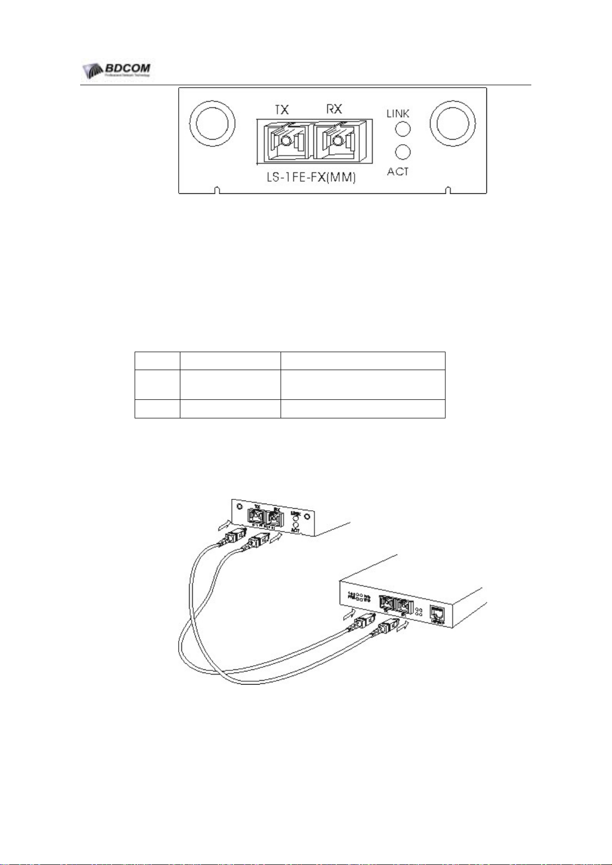
3.3 Installing Single-port 100Base-FX(MM) Ethernet Module.....................................................................................6
3.3.1 Overview...................................................................................................................................................6
3.3.2 LS-1FE-FX(MM) Ethernet Module Connection with External Device........................................................7
3.4 Installing Single-port 1000Base-TX Ethernet Module............................................................................................7
3.4.1 Overview...................................................................................................................................................8
3.4.2 LS-1GE-TX Ethernet Module Connection with External Device................................................................9
3.5 Installing Single-port 1000Base-LX Ethernet Module............................................................................................9
3.5.1 Overview...................................................................................................................................................9
3.5.2 LS-1GE-LX Ethernet Module Connection with External Device..............................................................10
3.6 Installing Single-port 1000Base-SX Ethernet Module.........................................................................................10
3.6.1 Overview.................................................................................................................................................10
3.6.2 LS-1GE-SX Ethernet Module Connection with External Device.............................................................11
3.7 Installing Single-port Gigabit GBIC Module Extension........................................................................................11
3.7.1 Overview................................................................................................................................................. 11
3.7.2 LS-1GE-SX Module and Connection to the External Device..................................................................12
3.7.3 Insert GBIC Module.................................................................................................................................12
- I -

BDCOM switch module Hardware Installation Guide
Chapter 1 Overview of BDCOM Module
1.1 Module Overview
This section explains the interface module of the BDCOM switch.
BDCOM switch provides 2 extended Ethernet slots. Plug into the following interface
module as needed:
No. Type Name Label
1 Single-port 100Base-TX Ethernet Module LS-1FE-TX
2 Single-port 100Base-FX(SM) Ethernet Module LS-1FE-FX(SM)
3 Single-port 100Base-FX(MM) Ethernet Module LS-1FE-FX(MM)
4 Single-port 1000Base-TX Ethernet Module LS-1GE-TX
5 Single-port 1000Base-TX Ethernet Module LS-1GE-LX
6 Single-port 1000Base-SX Ethernet Module LS-1GE-SX
7 Single-port Gigabit GBIC Module Extension LS-1GBIC
1.2 Preparing to install the interface card
This chapter tells the care cases & preparing work before you begin, includs the
following sections:
Notes:
Please read this chapter carefully to avoiding possible injury to the body or any damage to the equipment.
1.2.1 Safety information
Put the router in clear,dust-free,dry and safe area.
Avoid using overdue external force to pull the power supply line, interface cable.
Do not wear loose clothing.
Wear safety glasses if you are working under any conditions that might be
hazardous to your eyes.
Suggest using UPS.
Safety warning.
Do not touch the unshielded telephone line.
Do not insert the tie-in of telephone into the ethernet by mistake.
- 1 -

BDCOM switch module Hardware Installation Guide
You should guarantee that the power of the power supply is powerful enough.
Use the power safety.
Do not insert/unlatch the cable with the power.
Static protection: please wear anti-static loop in the process of installation.
1.2.2 Tools & equipment needed
1. Tools
Flat-blade screw-driver.
Cross screw driver.
ESD-preventive wrist strap.
Cable.
Ethernet cable & special serial port interface cable
Console port cable.
Power cord.
2. Equipment
Configuration terminal (such as : analog PC)
- 2 -

BDCOM switch module Hardware Installation Guide
Chapter 2 Installing Module in BDCOM Switches
The section explains how to install interface module. Before installing interface module,
make sure the switch is turned off.
Note:
Interface module does not support hot plug. Hot plug may cause permanent damage to interface
module.
Operations:
(1) Turn off the power. To prevent damage caused by static, keep the switch and
personnel grounded.
(2) Unplug all the cables.
(3) Use a flat head screwdriver to remove the piece of iron on the interface
module (see the following picture). Do throw away the piece of iron.
(4) Put the interface module in the guiding track. Slide it into the switch. (Refer to
the illustration below.)
(5) Slide the interface module and align it to the switch.
(6) Use the flat head screwdriver fasten the interface module and the switch.
(7) The following chapters explain different interface module cable connections and
LED status. Refer to the corresponding chapters for external connection.
(8) After installation, start installing software.
- 3 -

BDCOM switch module Hardware Installation Guide
Chapter 3 Connecting Module to a Network
3.1 Installing Single-port 100Base-TX Ethernet Module
Single-port 100Base-TX Ethernet module (LS-1FE-TX) adopts RJ45 interface standard.
It supports 10/100Mbps auto-sense and auto-MDI/MDIX, which may realize Ethernet
message transmission at 140m.
3.1.1 Overview
Single-port 100Base-TX Ethernet module port supports 10/100M auto-sense and.
auto-MDI/MDIX. Transmission distance:
10Mbps: UTP 3/4/5/ (transmission distance is 140m)
100Mbps: UTP 5 (transmission distance is 140m)
Figuer 3-1 Front view of Single-port 100Base-TX Ethernet module panel
3.1.2 Information of interface card
1. Cable of interface card
Table 3-1 Definition of RJ45 pin
Pin NO. Description Name Note
1Data transmission positive TXD+ Output
2Data transmission negative TXD- Output
3Data receive positive RXD+ Input
6Data receive negative RXD- Input
Single-port 100Base-TX Ethernet module supports auto-MDI/MDIX. This is able to
adopt UTP5 to connect to other Ethernet device.
- 4 -

BDCOM switch module Hardware Installation Guide
2. Single-port 100Base-TX Ethernet Module LED
No. Name Note
1 LINK Indicate the connection status of RJ45.
2 ACT Indicate transmission of RJ45.
3.1.3 LS-1FE-TX Ethernet Module Connection with External Device
3.2 Installing Single-port 100Base-FX(SM) Ethernet Module
Single-port 100Base-FX(SM) Ethernet module (LS-1FE-FX(SM)) transform
100Methenet message into optical message. Fiber optic transmission lengthen the
transmission of Ethernet transmission.
3.2.1 Overview
The configured optic module decides the transmission distance of Single-port
100Base-FX(SM) Ethernet module. By using different optic module, we are able to
realize different transmission distances. The manufacturer default transmission
distance for Single-port 100Base-FX(SM) is 15km. Users may realize farther
transmission according to their needs.
Figuer 3-2 Single-port 100Base-FX(SM) Ethernet Module Panel
- 5 -

BDCOM switch module Hardware Installation Guide
1. Single mode Ethernet fiber optical transceiver module pin
TX: optical signal transferring end;
RX: optical signal receiving end.
2. Single-port 100Base-FX(SM) Ethernet Module LED
No. Name Note
1 LINK Indicate the connection status of the ports
2 ACT Indicate transmission of the ports
3.2.2 LS-1FE-FX(SM) Ethernet Module Connection with External Device
Connect the Single-port 100Base-FX(SM) Ethernet module TX to megabit single mode
Ethernet optic module RX and connect the Single-port 100Base-FX(SM) Ethernet
module RX to the megabit single mode Ethernet optic module TX.
3.3 Installing Single-port 100Base-FX(MM) Ethernet Module
Single-port 100Base-FX(MM) Ethernet module (LS-1FE-FX(MM)) transform
100Methenet message into optical message. Optic fiber transmission lengthen the
transmission of Ethernet transmission.
3.3.1 Overview
Single-port 100Base-FX(MM) Ethernet module can transfer 2km. Users may select
Single-port 100Base-FX(SM) Ethernet module to realize farther transmission.
- 6 -

BDCOM switch module Hardware Installation Guide
Figuer 3-3 Single-port 100Base-FX(MM) Ethernet Module
1. Multi-mode Ethernet fiber optical transceiver module pin.
TX: optical signal transferring end;
RX: optical signal receiving end.
2. Single-port 100Base-FX(MM) Ethernet Module LED.
No. Name Note
1 LINK Indicate the connection status of the
ports.
2 ACT Indicate transmission of the ports.
3.3.2 LS-1FE-FX(MM) Ethernet Module Connection with External Device
Connect the Single-port 100Base-FX(MM) Ethernet module TX to 100Base-FX(MM)
Ethernet fiber optical transceiver module RX and the RX to the TX.
3.4 Installing Single-port 1000Base-TX Ethernet Module
Single-port 1000Base-TX Ethernet module (LS-1GE-TX) adopts RJ45 interface
standard, which supports 10/100/1000Mbps auto-sense and auto-MDI/MDIX.
- 7 -

BDCOM switch module Hardware Installation Guide
3.4.1 Overview
Single-port 1000Base-TX Ethernet module port supports 10/100/1000M auto-sense
and auto-MDI/MDIX and adopts UTP 5 and is able to transfer 100m:
Figuer 3-4 Single-port 1000Base-TX Ethernet Module
1. Cable of interface card
Table 3-2 Definition of 1000Base RJ45 pin
Pin NO. Description Name Note
1Data transmission positive TXD1+ Output
2Data transmission negative TXD1- Output
3Data receive positive RXD1+ Input
4 Data transmission positive TXD2+ Output
5 Data transmission negative TXD2- Output
6Data receive negative RXD1- Input
7 Data receive positive RXD2+ Input
8 Data receive negative RXD2- Input
Single-port 1000Base-TX Ethernet module supports auto-MDI/MDIX. It is able to adopt
UTP 5 to connect to other Ethernet device.
2. Single-port 1000Base-TX Ethernet module LED
No. Name Note
1 LINK Indicate the connection status of RJ45.
2 ACT Indicate transmission of RJ45.
- 8 -
Inhaltsverzeichnis
Andere Bdcom Netzwerk-Router Handbücher
Beliebte Netzwerk-Router Handbücher anderer Marken

NETGEAR
NETGEAR FS526T - Switch Bedienungsanleitung

Korenix
Korenix JetNet 5710G Series Bedienungsanleitung

Automated Logic
Automated Logic ZN551 Betriebsanleitung

Cisco
Cisco ASR 1000 Series Bedienerhandbuch

EnGenius
EnGenius ESR-9710 Bedienungsanleitung

Cisco
Cisco 805 Series Bedienungs- und Sicherheitshinweise


