Bicom Systems OfficeBox Bedienungsanleitung

Home
PBXware
SERVERware
TELCOware
SIPmon
SIPProt
Desktop & Mobile
BRM
UADs
Appliances
EOL
From Bicom Systems Wiki
Contents
1 Introduction
■
2 Chapter 1. OfficeBOX Installation Guide
■
2.1 Introduction
■
2.2 Requirements
■
2.3 Important Safeguard
■
2.4 Overview
■
2.5 Installation
■
2.6 Software Setup
■
2.7 PBXware image flashing procedure
■
Introduction
Installation guide takes you through the process of setting up the officeBOX appliance, this
takes a small amount of time after which you can use your officeBOX appliance.
Chapter 1. OfficeBOX Installation Guide
Copyright (c) 2003-2008 Bicom Systems Ltd. All rights reserved. Third Party and Open Source
softwares are included. For more details on these please see EULA at
www.bicomsystems.com/eula/
DOCUMENTATION IS PROVIDED "AS IS" AND ALL EXPRESS OR IMPLIED CONDITIONS,
REPRESENTATIONS AND WARRANTIES, INCLUDING ANY IMPLIED WARRANTY OF
MERCHANTABILITY, FITNESS FOR A PARTICULAR PURPOSE OR NONINFRINGEMENT, ARE
DISCLAIMED, EXCEPT TO THE EXTENT THAT SUCH DISCLAIMERS ARE HELD TO BE
LEGALLY INVALID

Introduction
Installation guide takes you through the process of setting up the officeBOX appliance, this
takes a small amount of time after which you can use your officeBOX appliance.
Requirements
Requirements for the usage of officeBOX are:
10/100Base TCP/IP based local area network (LAN)
■
One of the following web browsers:
■
Internet explorer 6.0+
■
Firefox 1.0+
■
Opera 9.0+
■
To manage officeBOX from the web administration interface, web browser must support
Javascript, CSS and you must enable cookies.
Network parameters which include officeBOX IP address, the subnet mask of your network
■
and a gateway or router address if communicating with other networks can be obtained by:
Connecting a monitor to officeBOX and obtaining IP from command prompt
■
Installing the PBWware Finder on a Windows machine which is also connected to the
■
same network. PBXware Finder can be obtained at:
http://downloads.bicomsystems.com/pbxware_finder/pbxware-finder-1.0.exe
Obtaining it from the DHCP server
■
Important Safeguard
For your safety, please read all the instructions regarding officeBOX appliance.
a) Safety precautions

For your protection when setting up the equipment, observe:
All cautions and instructions marked on the equipment should be followed
■
Make sure that your power source voltage and frequency matches the one required by
■
your equipment
Never insert objects through openings on the equipment. This can be dangerous and can
■
damage the equipment.
b) Symbols
Following symbols may appear in this guide:
Caution sign: There is a risk of injury and damage to the equipment.
Warning sign: Hazardous voltages are present. To reduce the risk of electrical shock follow the
instructions.
Tip sign: Useful suggestions or tips that can help you in the setup procedure.
c) Power source and power cords
Make sure that your power source voltage and frequency matches the one required by your

equipment.
officeBOX is designed to work with single-phase power systems. To reduce the risk of electrical
shock, do not plug the equipment into any other power system. If you are not sure what kind of
power system your facility has, contact the facility manager or a qualified electrician.
Your officeBOX power supply is shipped with a grounded type power cord, so to reduce the risk
of electrical shock, always plug the cord into a grounded power outlet.
Not all power cords have the same current ratings, and not all power cords fit your officeBOX
power supply. Thus the usage of other power cords is not recommended.
d) Electrical Shock
To reduce the risk of electrical shock, do not disassemble or tamper in any way with the power
supply. Opening the power supply may expose you to dangerous voltage, and incorrect
reassembly will damage your equipment
e) Top cover
In order to add cards or internal storage, first you must remove the top cover. Make sure to
place the top cover back before turning on the appliance.
Do not work with the officeBOX without its top cover in place. Failing to do so may cause injury
and equipment damage.

f) Equipment modifications
Do not make any hardware modifications to the equipment. Bicom Systems is not responsible for
any damage or injury as a result of the equipment modification.
g) Ventillation
Although officeBOX does not use active cooling, it will not overheat within defined room
temperatures. Nevertheless, good ventillation space is required for the proper working of the
appliance. Openings on the appliance must not be covered or blocked and should be kept free
from dust.
h) Placement
Openings on the top cover are meant as a ventillation of any small amount of exccess heat that
is not transfered to the side aluminium cooler, and they should be free. That means that you
should place the appliance in a well vented place.
Do not put the appliance near a radiator or any other heat emmiting device. Doing so can cause
your appliance to overheat and malfunction.
i) Regulations and information
This device complies with the CE and FCC Rules and Regulations which can be obtained from
the supplier
Overview
Installation of the officeBOX appliance takes place in three steps:
Installation, explains the mounting process and physical connection to the network and
■
to a power source.
Adding new functionality by installing various cards.
■
Software Setup, explains the process of setting up the appliance in a network
■
environment using the web-based Setup Wizard

Front view of the officeBOX™
Overview/Front view of the
officeBOX
Figure 1. Front view of the officeBOX appliance.
1. Hard Disk activity LED
2. On/Off Button
Rear view of the officeBOX™
Overview/Rear view of the
officeBOX
Figure 2. Rear view of the officeBOX appliance.
1. PS/2 connector for connecting a mouse
2. PS/2 connector for connecting a keyboard
3. Serial connector
4. VGA for connecting a monitor if needed
5. Ethernet connector for LAN network integration
6. Ethernet connector for WAN network integration

7. Four USB connectors for additional USB devices
8. Line Out jack
9. Line In jack
10. Microphone jack
11. Three PCI mounting places of which you use first and second.
12. Power Supply connector
Installation
In this chapter we will guide you through the process of adding new functionality, mounting of
the appliance and connecting it to the network and power supply.
First, we will explain how to expand the appliance's functionality in the subchapter "Installing
PCI cards," where details about adding cards will be presented. In the chapter OfficeBOX
mounting we will explain where and how an officeBOX appliance can be mounted.
Software setup is described in another document which is also available from the website.
Installing PCI cards
Although officeBOX is a fully functional communication appliance, new functionality can be
added by installing various PCI cards. You can add PSTN, ISDN or E1/T1 functionality of your
choice, and with an enclosed PCI riser it is possible to add two cards into officeBOX.
A list of supported devices is available on Bicom Systems website:
http://downloads.bicomsystems.com/pbxware_finder/pbxware-finder-1.0.exe
The procedure of installing new cards is simple and we will take you through it step by step.
Top cover removal
Remove the top cover by removing three screws, one on the right side and two on the left side.
Then, by placing four fingers of both hands on the cover and using thumbs to push the front of
the appliance, pull the cover slightly towards yourself as in Figure 12. Once the cover is
released from its locks, you can take it off.

When you take the PCI riser out, be sure not to lose two plastic little tubes that are used as a
spans between the two PCI slots on the riser. The screws that hold the riser inside the appliance
go through the plastic tubes, so they are important when re-inserting the riser.
PCI card mounting
Remove the screws from the PCI card mounting from the back of the appliance and take it out.
PCI card mounting
Figure 5. Rear view of officeBOX
When PCI card mounting is out, remove the metal slot cover from slot 1 or 2, depending upon
the card placement on the PCI riser.
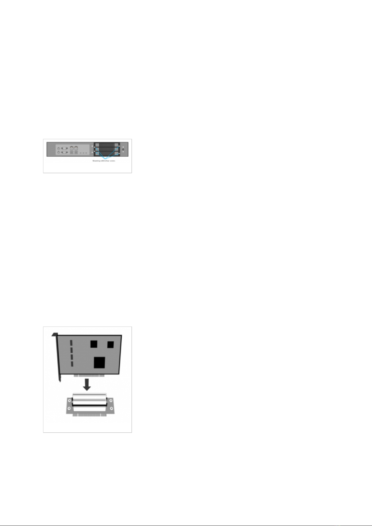
Inserting a PCI card
Inserting a PCI card

Figure 6. Inserting a card
Insert desired card into the PCI riser. Attach the PCI card mounting to the card which is
inserted into the PCI riser, using the screw which was holding the cover on the mounting.
Figure 7. Everything put together
Fitting everything into officeBOX
When the PCI card mounting is attached to a card in the PCI riser, put the spans back between
the PCI slots, and insert the screws that attach it to the appliance through the holes as shown in
Figure 8. (card and mounting are omited for simplicity).
Figure 8. is showing top view of the PCI riser which means that the screws which hold it, must
be placed from the top, so they can attach everything properly to the appliance.
Andere Handbücher für OfficeBox
1
Inhaltsverzeichnis
Beliebte Telefonanlage Handbücher anderer Marken

Allo.com
Allo.com Nano 2 Bedienungsanleitung

ZYCOD
ZYCOD ZX50 Bedienungsanleitung

Panasonic
Panasonic KX-TDA100BX Bedienungsanleitung

LV switch
LV switch IPPBX800 Gebrauchsanweisung

Edge-Core
Edge-Core VST3305 Bedienungsanleitung

Panasonic
Panasonic KX-T7625 - Digital Proprietary Speakerphone 24... Bedienungsanleitung

Rauland-Borg
Rauland-Borg Telecenter IV Bedienungsanleitung

Grandstream Networks
Grandstream Networks UCM6208 Bedienungsanleitung

ATCOM
ATCOM IPPBX IP02 Bedienungsanleitung

Panasonic
Panasonic KX-TVS50 - 2 Port Voicemail System Bedienungsanleitung

bintec elmeg
bintec elmeg elmeg hybird 600 Bedienungsanleitung

Panasonic
Panasonic KX-NS300 Bedienungsanleitung


