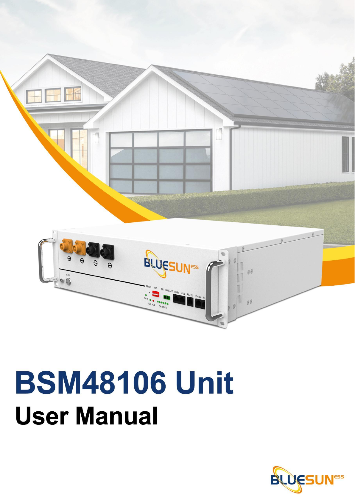
BlueSun BSM48106 Bedienungsanleitung

______________________________________________BSM48106 USER MANUAL

______________________________________________BSM48106 USER MANUAL
Content
1. Introduction ............................................................................................................... 3
1.2 Brief Introduction ..............................................................................................3
1.3 Product Properties ............................................................................................4
2. Product Specification ................................................................................................. 5
2.1 Size and Weight .................................................................... 错误!未定义书签。
2.2 Performance Parameter ................................................................................... 5
2.3 Equipment Interface Instruction .......................................................................6
2.4 Battery Management System(BMS) ..................................... 错误!未定义书签。
2.4.1 BMS Protection and Alarm ......................................... 错误!未定义书签。
3. Installation and Configuration ................................................................................. 10
3.1 Preparation for installation .............................................................................10
3.1.1 Safety Requirement .............................................................................. 10
3.1.2 Environmental requirements ................................................................10
3.1.3 Tools and data .......................................................................................11
3.1.4 Technical preparation ........................................................................... 11
3.1.5 Unpacking inspection ............................................................................11
3.2 Equipment installation ....................................................................................13
3.2.1 Installation Steps ...................................................................................13
4. Installation and Configuration ................................................................................. 18
4.2 Alarm description and processing .................................................................. 19

______________________________________________BSM48106 USER MANUAL
1. Introduction
1.1 Important Safety Instructions
1.2 Brief Introduction
Danger!
Please do not put the battery into water or fire, in case of explosion or any other
situation that might endanger your life.
Please connect wires properly while installation, do not reverse connect.
To avoid short circuit, please do not connect positive and negative poles with
conductor on the same device.
Please avoid any form of damage to battery, especially stab, hit, trample or strike.
Danger!
Please shut off the power completely when removing the device or reconnecting wires
during the daily use or it could cause the danger of electric shock.
Please use dry powder extinguisher to put out the flame when encountering a fire
hazard, liquid extinguisher could result in the risk of explosion.
For your safety, please do not arbitrarily dismantle any component in any
circumstances. The maintenance must be implemented by authorized technical
personnel or our company’s technical support. Device breakdown due to unauthorized
operation will not be covered under warranty.
Caution!
Our productshave been strictly inspected before shipment. Please contact us if you
find any abnormal phenomena such as device outer case bulging.
The product shall be grounded properly before use in order to ensure your safety.
To assure the proper use please make sure parameters among the relevant device are
compatible and matched.
Please do not mixed-use batteries from different manufacturers, different types and
models, as well as old and new together.
Caution!
Ambient and storage method could impact the product life span, please comply with
the operation environment instruction to ensure device works in proper condition.
For long-term storage, the battery should be recharged once every 6 months, and the
amount of electric charge shall exceed 80% of the rated capacity.
Please charge the battery in 18 hours after it fully discharged or over-discharging
protection mode is activated.
Formula of theoretical standby time: T=C/I (T is standby time, C is battery capacity, I is
total current of all loads).

______________________________________________BSM48106 USER MANUAL
BSM48106 lithium iron phosphate battery system is a standard battery system unit, customers can
choose a certain number of BSM48106 according to their needs, by connecting parallel to form a
larger capacity battery pack, to meet the user's long-term power supply needs. The product is
especially suitable for energy storage applications with high operating temperatures, limited
installation space, long power backup time and long service life.
1.3 Product Properties
BSM48106 energy storage product’s positive electrode materials are lithium iron phosphate,
battery cells are managed effectively by BMS with better performance, the system’s features
as below:
The whole module is non-toxic, non-polluting and environmentally friendly;
Cathode material is made from LiFePO4 with safety performance and long cycle life
Battery management system with better performance, possesses protection
function like over-discharge, over-charge, over-current, abnormal temperature.
Self-management on charging and discharging, Single core balancing function.
Intelligent design configures integrated inspection module.
Flexible configuration, multiple battery modules can be in parallel for expanding capacity
and power.
Flexible configurations allow parallel of multi battery for longer standby time.
Self-ventilation with lower system noise.
Less battery self-discharge, then recharging period can be up to 10 months during the
storage.
No memory effect so that battery can be charged and discharged shallowly.
With wide range of temperature for working environment, -20℃~ +55℃, circulation
span and discharging performance are well under high temperature.
Small size and light weight, standard of 19-inch embedded designed module is comfortable
for installation and maintenance;

______________________________________________BSM48106 USER MANUAL
2. Product Specification
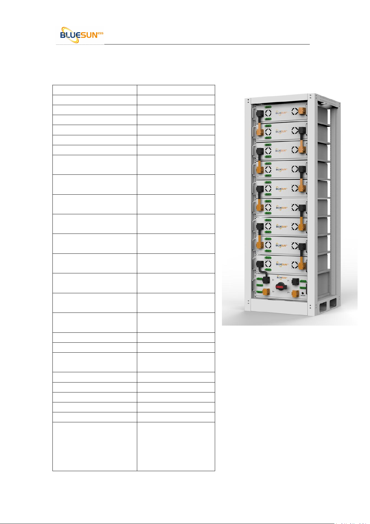
2.1 Performance Parameter
Table 2-2 BSM48106 performance parameter
Basic Parameters
BSMH-409.6V-106AH
Nominal Voltage (V)
409.6V
Nominal Capacity (KWH)
43.4176
Usable Capacity (KWH)
39.07584
Battery Controller Name
BSMC-1000-120
Battery Module Name
BSMH48106
Battery Module Quantity
8
Battery Module
Capacity(KWH)
5.4272
Battery Module Voltage(V
dc)
51.2
Battery Module Capacity
(Ah)
106
Battery System Charge
Voltage(V dc)
448
Battery System Charge
Current(Normal)
50
Battery System Charge
Current(Max)
106
Battery System Discharge
lower-Voltage(Vdc)
384
Battery System Discharge
Current (Standard)
50
Battery System Discharge
Current(Normal)
100
Efficiency
96%
Depth of Discharge
RS485/RS232/CAN
Working Temperature
0℃~50℃Charge
-10℃~50℃Disharge
Shelf Temperature
-20℃~60℃
Communicaiton
RS485/CAN
Certification
CE/IEC/UL/UN38.3/MSDS
Design Life
10 years+
Cycle Life
>6000
Other:
1)Battery Controller
Dimensions (W*D*H)
2)Battery Module
Dimensions(W*D*H)
450*412*133
450*412*177.8

______________________________________________BSM48106 USER MANUAL
2.2 Battery Module
No.
Product Type
BSMH48106
1
Cell Technology
Li-ion(LFP)
2
Battery Module Capacity (KWH)
3
Battery Module Voltage (Vdc)
4
Battery Module Quantity (PCS)
5
Battery Cell Voltage(Vdc)
6
Battery Cell Capacity (AH)
7
Battery Module Cell Quantity in
Series(pcs)
8
Battery Module Charge Voltage(Vdc)
9
Battery System Charge
Current(Standard)
10
Battery Module Charge Current(Normal)
11
Battery Module Charge Current(Max)
12
Battery Module Discharge
Lower-Voltage(Vdc)
13
Battery System Discharge Current
(Standard)
14
Battery Module Charge Current
(Normal)
15
Battery Module Charge Current (Max)
16
Efficiency
17
Depth of Discharge
18
Dimension(W*D*H, mm)
19
Communication
20
Protection Class
21
Weight
22
Operation Life
23
Operation Cycle Life
24
Operation Temperature
25
Storage Temperature
Product Certificate

______________________________________________BSM48106 USER MANUAL
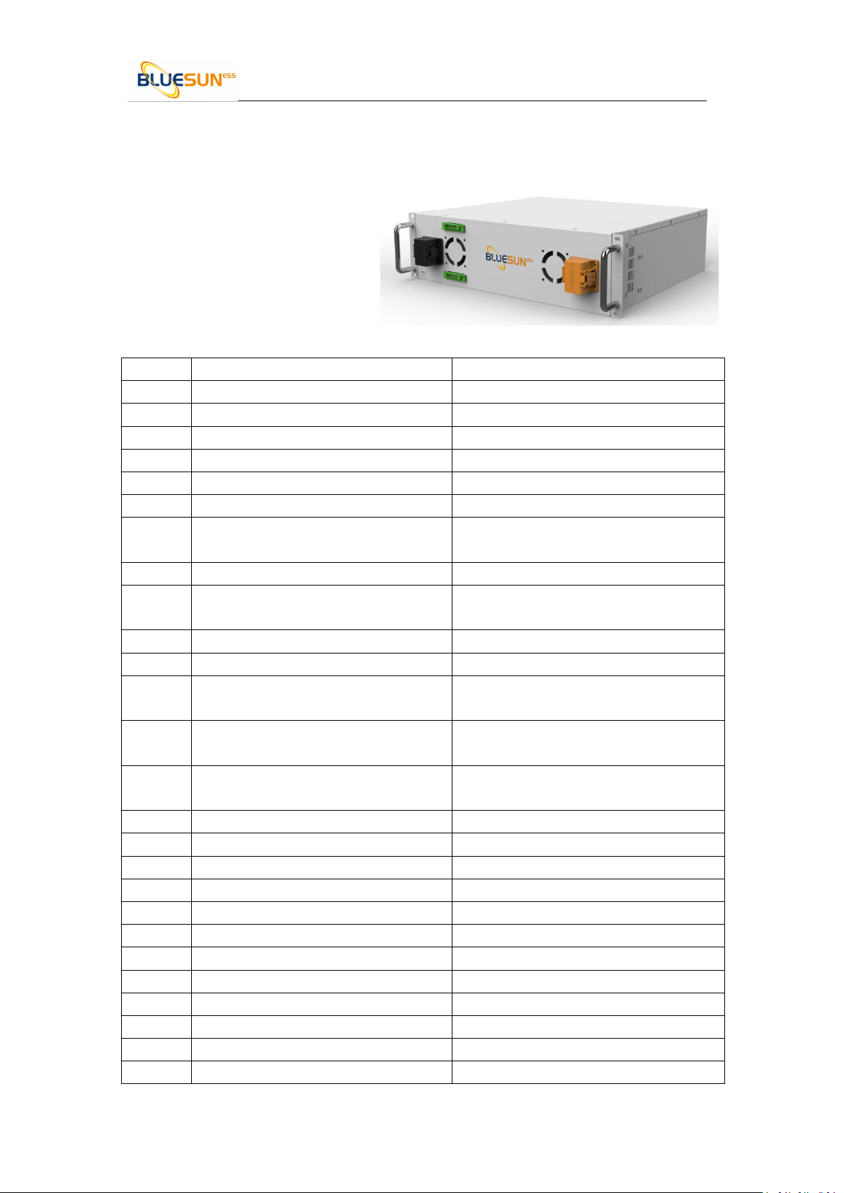
2.2.1 Battery Module Information
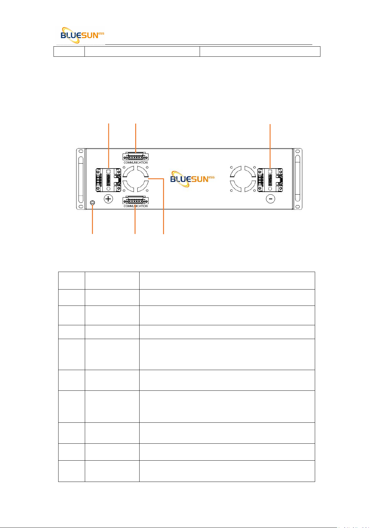
2.2.2 Battery Module Front Interface
Table 2-3 Interface Definition
Item
Name
Definition
1
Positive socket
Battery output positive or parallel positive line
2
Communication
Port
Support RS485 communication between battery module, and
control module
3
Negative socket
Battery output positive or parallel positive line
4
SW (battery
wake/ sleep
switch)
When the "OFF/ON" switch button is in the ON state, press
and hold this button for 3 seconds to put the battery into the
power-on or off state.
5
SOC
The number of green lights shows the remaining power. Table
2-3 for details.
6
ALM
Red light flashing when an alarm occurs, red light always on
during protection status. After the condition of trigger
protection is relieved, it can be automatically closed
7
RUN
Green light flashing during standby and charging mode.
Green light always on when discharging.
8
COM
Communication cascade port, support RS23 2
9
CAN/485
Communication cascade port, support CAN/ RS485
communication ( factory default CAN communication)
Transfer Certificate
1 2 3
4 5 6

______________________________________________BSM48106 USER MANUAL
10
DRY CONTACT
/
11
Negative socket
Battery output negative or parallel negative line
12
Grounding
Shell ground connection
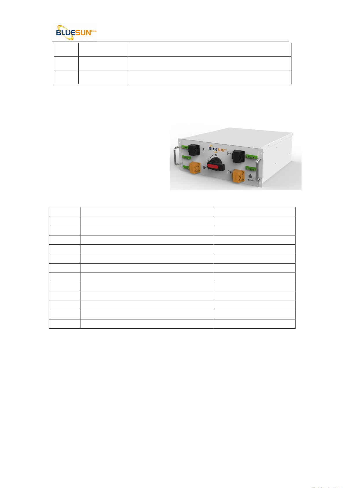
2.3 Control Module (internal power supply)
2.3.1 Control Module information
Item
Product Type
BSMC-1000V-120A
1
Related Product
1000V 120A
2
AC Supply
3
System Operation Voltage (Vdc)
4
Operation Current (Max.) (A)
5
Self-consumption Power(W)
6
Dimension (W* D* H, mm)
7
Communication
8
Protection Class
9
Weight(kg)
10
Operation Life
11
Operation Temperature
12
Storage Temperature

______________________________________________BSM48106 USER MANUAL
2.3.2
Control Module has two types: internal and external power supply
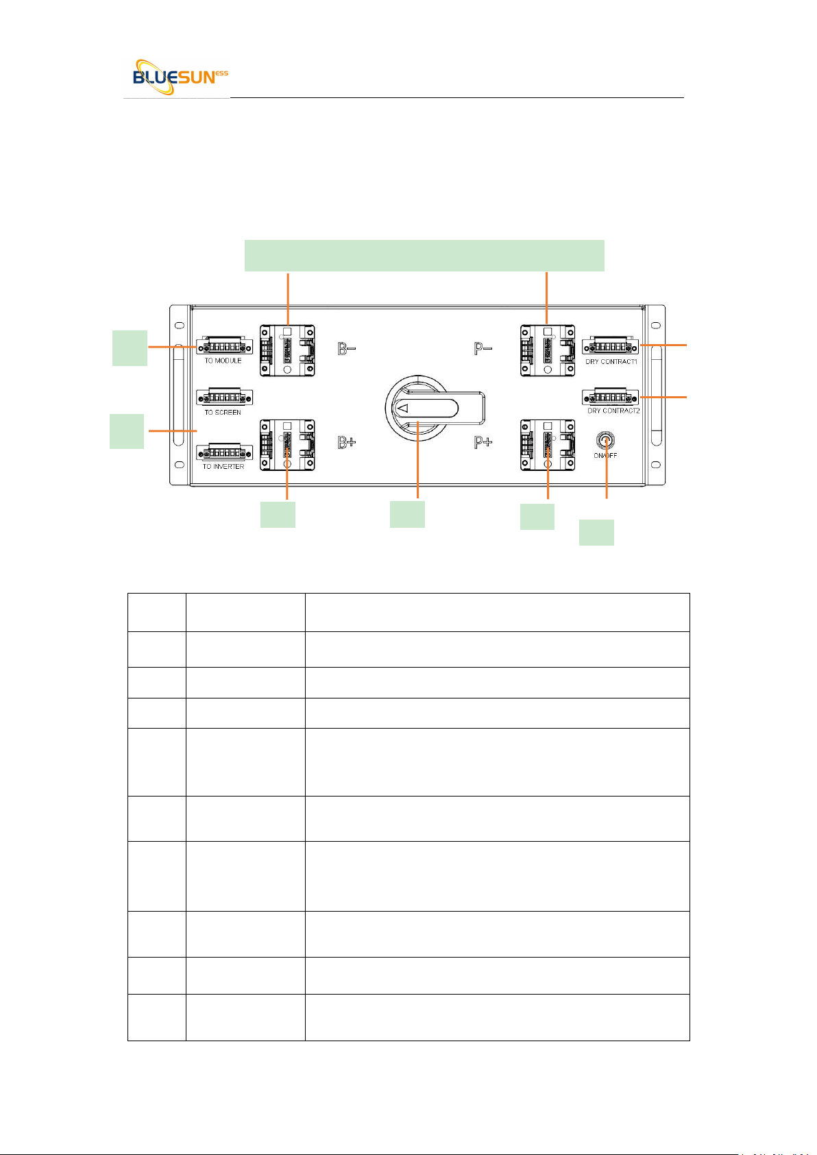
Control Module (BSMC-1000-250) Front Interface
Table 2-3 Interface Definition
Item
Name
Definition
1
Power switch
OFF/ ON,
must be in the " ON" state when in use
2
Positive socket
Battery output positive or parallel positive line
3
ADD
DIP switch
4
SW (battery
wake/ sleep
switch)
When the "OFF/ON" switch button is in the ON state, press
and hold this button for 3 seconds to put the battery into the
power-on or off state.
5
SOC
The number of green lights shows the remaining power. Table
2-3 for details.
6
ALM
Red light flashing when an alarm occurs, red light always on
during protection status. After the condition of trigger
protection is relieved, it can be automatically closed
7
RUN
Green light flashing during standby and charging mode.
Green light always on when discharging.
8
COM
Communication cascade port, support RS23 2
9
CAN/485
Communication cascade port, support CAN/ RS485
communication ( factory default CAN communication)
1 2
3
4
5
6
7
8
9
10

______________________________________________BSM48106 USER MANUAL
10
DRY CONTACT
/
11
Negative socket
Battery output negative or parallel negative line
12
Grounding
Shell ground connection
1. Installation and Configuration
1.1 Preparation for installation
3.1.1 Safety Requirement
This system can only be installed by personnel who have been trained in the power supply
system and have sufficient knowledge of the power system.
The safety regulations and local safety regulations listed below should always be followed during
the installation.
All circuits connected to this power system with an external voltage of less than 51.2V
must meet the SELV requirements defined in the IEC60950 standard.
If operating within the power system cabinet, make sure the power system is not
charged. Battery devices should also be switched off.
Distribution cable wiring should be reasonable and has the protective measures to avoid
touching these cables while operating power equipment.
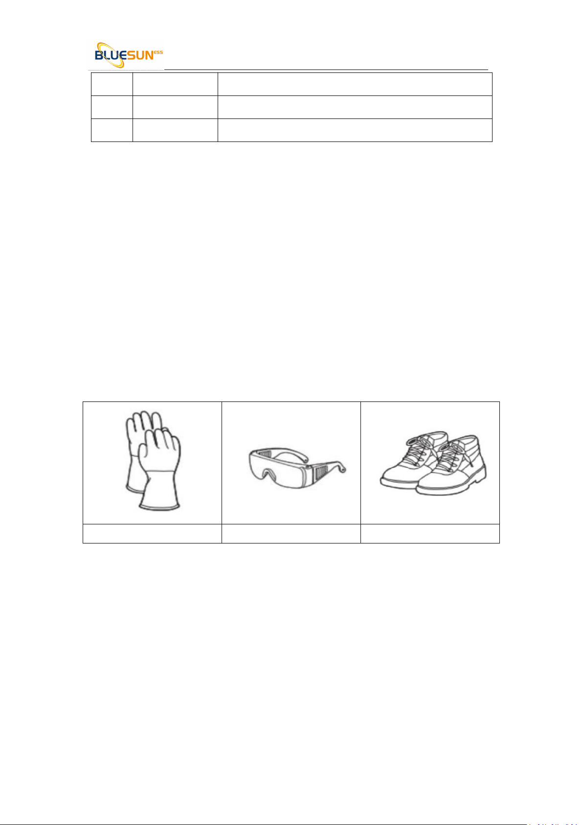
when installing the battery system, must wear the protective items below:
The isolation gloves
Safety goggles
Safety shoes
3.1.2 Environmental requirements
Working temperature: -20℃~ +55℃
Charging temperature range is 0oC~+55℃,
Discharging temperature range is -20℃~+55℃
Storage temperature: -10℃~ +35℃
Relative humidity: 5% ~ 85%RH
Elevation: no more than 4000m
Operating environment: Indoor installation, sites avoid the sun and no wind, no conductive
dust and corrosive gas.
And the following conditions are met:
Installation location should be away from the sea to avoid brine and high humidity
environment.
Inhaltsverzeichnis
Beliebte Batteriepack Handbücher anderer Marken

IOGear
IOGear GBP24V Series Bedienungsanleitung

Inventus Power
Inventus Power PROTRXion S-12V100-TRX-HD Bedienungsanleitung

Clas Ohlson
Clas Ohlson PW-290A Bedienungsanleitung

EINHELL
EINHELL MULTI-Ah Power X-Change Plus Bedienungsanleitung

Samsung
Samsung EB-U3300 Bedienungsanleitung

ECTIVE
ECTIVE LC Series Bedienungsanleitung