Canadian Spa Fraser Bedienungsanleitung
Fraser Gazebo - Assembly Instructions
www.canadianspacompany.com
• Two louvred sides
• Skylight
• Rounded corners with smoked acrylic
windows
• ABS roof
• Easy ‘nut and bolt assembly
• Bar
• 10’ x 10’ x 10’ (290 x 290 x 285 cm.)
• 4 stools with seat covers (optional)
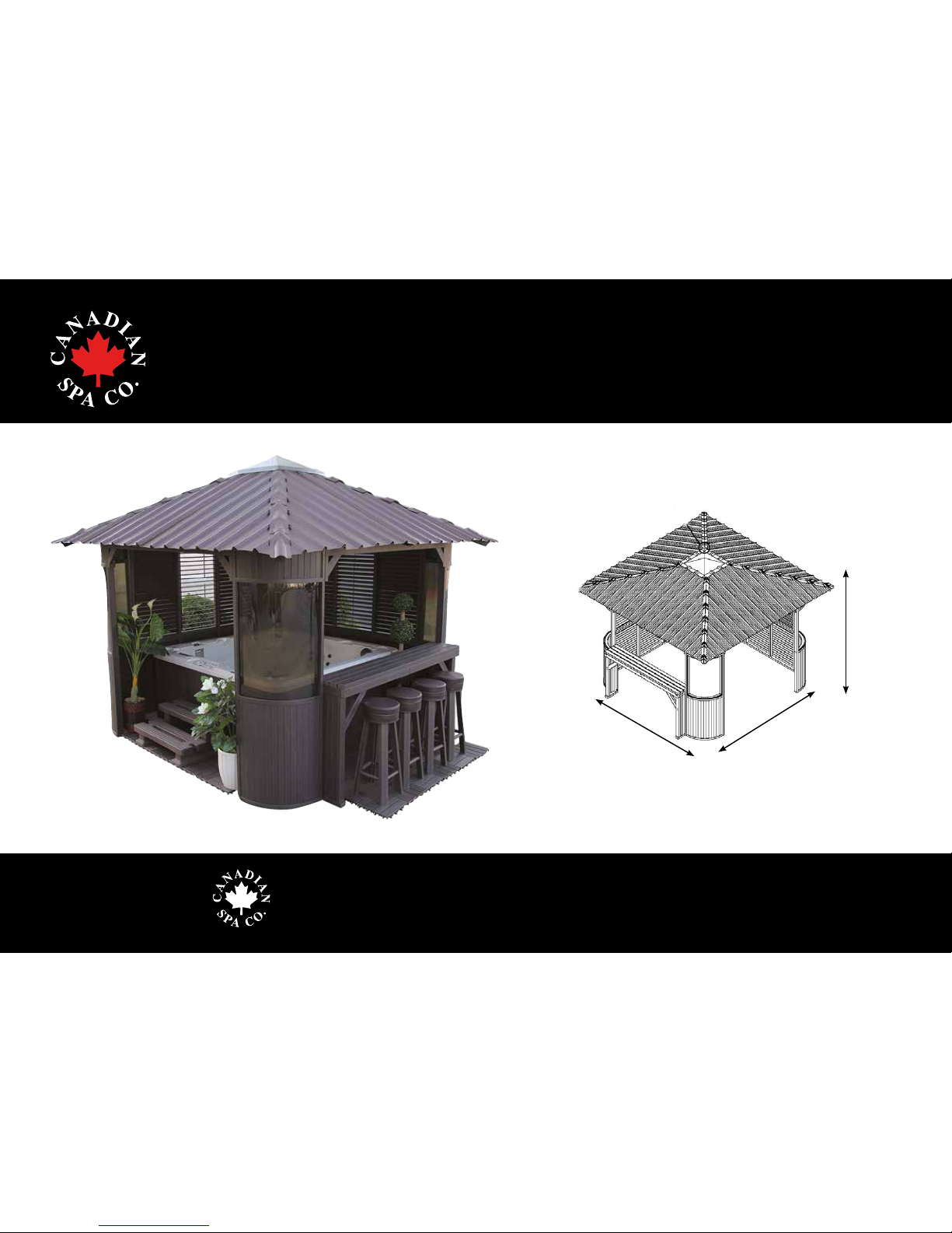
Freestanding Gazebo in synthetic wood with
Bar counter and Stools (optional)
Fraser Gazebo - Assembly instructions
Assembly instructions for: Fraser Gazebo • Bar counter
285 cm
290 cm
290 cm

Fraser Gazebo - Assembly Instructions
www.canadianspacompany.com
Parts List:
PART:
Gazebo corner(s)
Gazebo louvred wall panel(s)
Gazebo bottom wall panel(s)
Bar table top
Bar table legs
Bar stool seat(s)and covers (optional extra)
Bar stool legs (optional extra)
Gazebo corner connecting beam(s)
Roof Hip rafter(s)
Roof Rafter(s)
Roof Joist(s)
Roof Crossmember(s) - Long
Roof Crossmember(s) - Short
Skylight & skylight collar
Corner joist bracket (triangular)
Roof frame joists
Roof tiles: 4x centre tiles/ 4 x triangular tiles
Roof Hip tile(s) x 4
Screws & additional parts*
ITEM:
1
2
3
4
5
6
7
8
9
10
11
12
13
14
15
16
17
18
19
CARTON QTY:
1
1
1
1
1
1
1
1
1
1
1
1
1
1
1
1
1
1
1
QTY (PIECES):
4
2
2
5
2
4
50
2
8
8
8
8
8
3
4
4
12
4
22
* SCREWS & ADDITIONAL PARTS:
A. 90º Bracket 12pcs (a1.), Straight bracket 12pcs (a2.), 151º Bracket 12pcs (a3.)
B. 6mm Allen key 1pc, White colloidal part 10pcs, Hexagonal bolt (M8*50mm) 46pcs
C. Tapping screws (M5*60mm) 42pcs/bag, Tapping screw (M5*50mm) 208pcs/bag,
Tapping screw (M4*50mm) 40pcs/bag, Tapping screw (M4*25) 70pcs/bag
D. Flat screws: M4*50 x 30pcs/bag, M4*25 x 296pcs/bag,
E. Bolts: M8*90 x 28pcs/bag, M8*80 x 20pcs/bag
F. Washers: M8 x 100pcs/bag, M8 Nut x 100pcs/bag, White washers x 150pcs/bag
G. Screw M12*70mm x 6pcs/bag, Rubber plug x 80pcs/bag
H. Window Sealant x 1pc, Sealant gun x 1pc
I. Instruction Manual x 1
1
2
8
9
10
12
13
17
14
18
15
16
11
3
4
5
6
7
a1 a2
a3

Fraser Gazebo - Assembly Instructions
www.canadianspacompany.com
Parts breakdown by section:
1. The Wall Structure:
- Gazebo corner(s) x 4
- Gazebo louvred window panel(s) x 2
- Gazebo bottom window panel(s) x 2
- Gazebo corner connecting beam(s) x 2
- Hexagonal screws (M8*50) x 40
- Self tapping screws (CT-M5*50) x 12
2. The Roof:
- Corner joist bracket (triangular) x 4
- Roof Frames x 8
- Roof Rafters x 8
- Roof Hip rafter(s) x 8
- Roof Joist(s) x 8
- Roof Crossmember(s) - Long x 8
- Roof Crossmember(s) - Short x 8
- Skylight collar x 1
- Skylight x 1
- 90º Bracket x 12
- Straight bracket x 12
- 151º Bracket x 12
- Triangular roof tiles (LEFT) x 4
- Triangular roof tiles (RIGHT x 4
- Straight roof tiles x 4
- Corner Ridge (Hip) tiles x 4
3. The Bar:
- Bar legs x 2
- Bar table top x 1
- Brackets x 4
- Hexagonal screws (M8*50) x 4
- Self tapping screws (CT-M5*50) x 8
4. Bar Stools (4):
- Stool legs x 16
- Stool seats x 4
- Stool padded seat cover x 4
- Leg braces (short) x 16
- Leg braces (medium) x 8
- Leg braces (long) x 8
- Bar stool foot x 16
- Self tapping screws (CT-M4*50) x 32
- Self tapping screws (CT-M4*25) x 64
The main sections:
The Fraser Gazebo is comprised of 4 main sections: 1.The Wall Structure, 2.The Roof, 3.The Bar, 4. Bar Stools x 4 (optional extra)
Please check that you have ALL the parts you need before assembling the gazebo.
Tools (suggested) you will need:
1. Allen key (Included), 2. Power drill + drill bits,
3. Philips screwdriver, 4. Spanner(s), 5. Spirit level,
6. Mallet, 7. ‘C’ Clamp

Fraser Gazebo - Assembly Instructions
www.canadianspacompany.com
Before you assemble Gazebo:
Access to power and water for Spa* / Gazebo
Before you take delivery of your Fraser Gazebo (and Spa) please take the time to decide where
you want the Gazebo to be positioned with a view to access to electricity and water.
* Photo shows hot tub being lled up through the Filter basket (recommended).
Solid Base
Build a solid base for your Gazebo/Spa to sit on. The overall area should be in excess of 3 x 3
metres plus additional perimeter of 0.5 meter around the outside of the structure.
Gazebo perimeter clearance
Ideally the Gazebo should be positioned at least a metre away from a neighbouring fence or
hedge to allow sufcient space for manoeuvring and assembling the structure.
Orientate Gazebo
Decide how you want your Gazebo to be orientated: Your spa has two ‘louvred sides and two
‘open’ sides, one of the open sides will have the ‘Bar’ attached and the other ‘open side is to
gain entry into the spa. The bar can be positioned between corners A-B, B-C, C-D.
Cover lifter clearance
As you enter the main ‘open’ side of the Gazebo decide in advance if you want your hot tub
cover lifter to open from the ‘left’ or ‘right’ hand side and then make sure you have sufcient
clearance within the structure for ‘lifting’ and closing the spa cover.
PLEASE READ CAREFULLY BEFORE ASSEMBLING GAZEBO
You will need at least 2 people to erect the Gazebo. Please check that you have ALL the parts you need before assembling
the gazebo (DO NOT leave Gazebo parts exposed to extreme heat prior to assembly as some materials may expand)
Fraser Gazebo - Assembly Instructions
www.canadianspacompany.com
Item No.
1
2
3
Quantity:
2 pcs
1 pc
4 pcs
4 pcs
8 pcs
Name:
Bar table leg
Bar table top
Support Brace
Hexagon bolt M8*50
Tapping screw M5*50
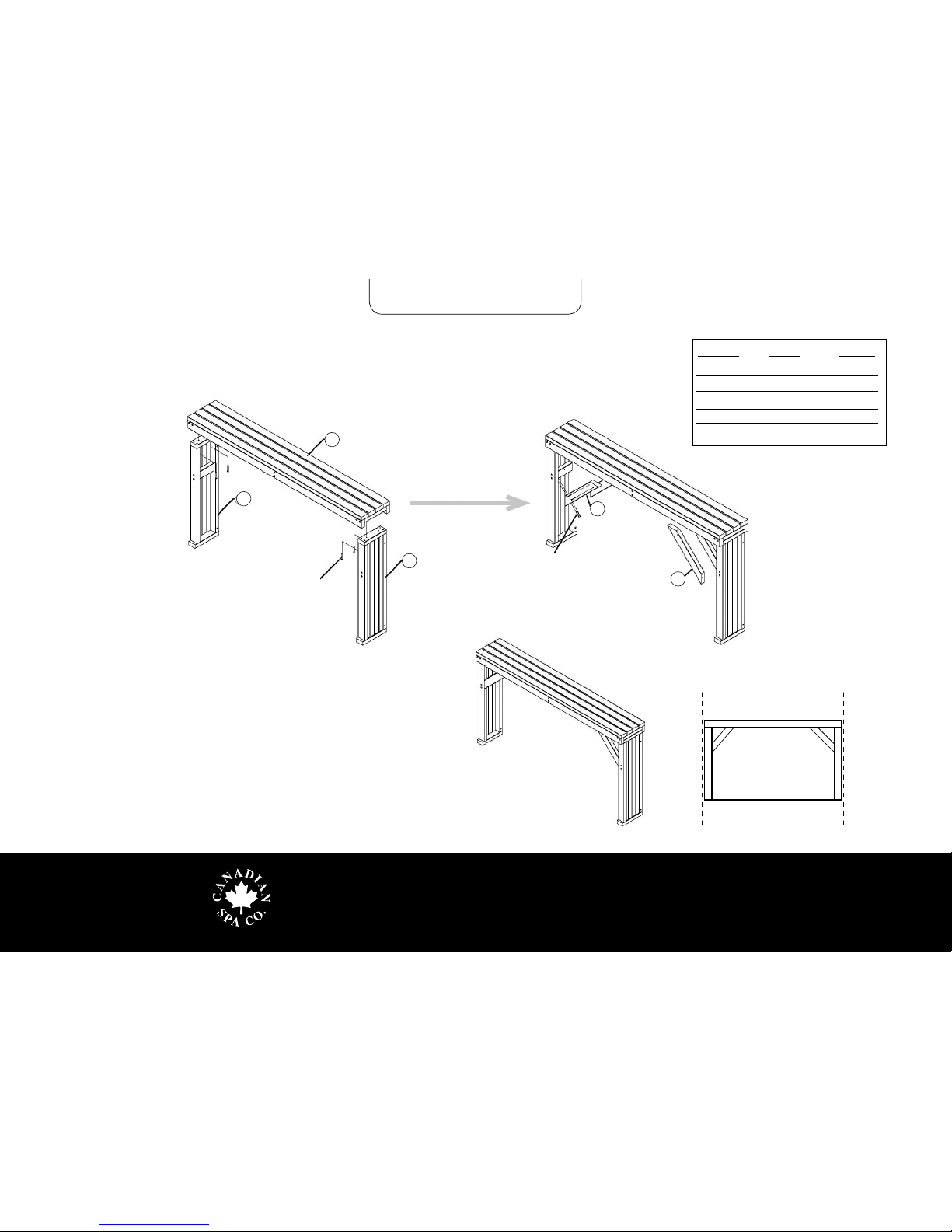
1. Bar assembly
2
1
1
3
3
Hexagon screw M8 * 50
Tapping screw M5 * 50
1. Use M8*50 bolts to connect bar table legs
and bar table top.
2. Add the Support Brace between the face and foot
using screw M5 * 50
IMPORTANT:
Make sure the
bar legs are at 90º
right angle to ensure a
perfect t to Gazebo walls
Fraser Gazebo - Assembly Instructions
www.canadianspacompany.com
Item No.
A
B
C
D
Quantity:
1 pc
1 pc
1 pc
1 pc
Name:
The right corner
of the bar table
The left corner of
the bar table
The corner of
louvred/panels
The right corner
of entrance
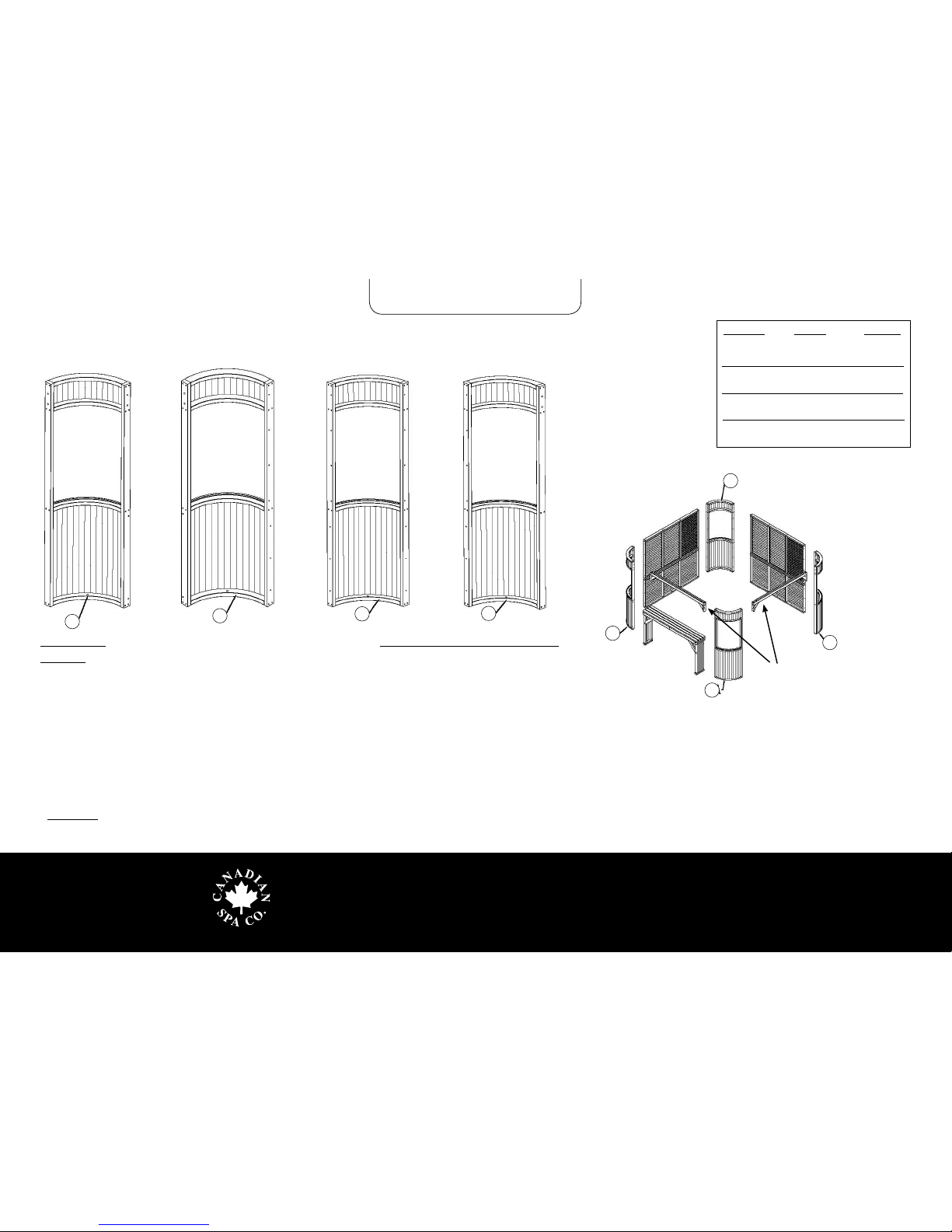
ABCD
2. Wall corner(s) assembly
IMPORTANT: The four corners of the Gazebo are labelled A, B, C, D. Start assembling your gazebo from
corner A and continue with corners B, C, D in a clockwise direction*
1. Corner A: There are 4 nut holes on the left edge and 2 on the right
2. Corner B: There are 7 holes on the left edge and 4 nut holes on the right
3. Corner C: There are 7 holes on the right and left edge.
4. Corner D: There are 2 nuts holes on the left edge and 7 holes on the right.
5.Connect the corner connecting beam between corner Aand B
6.Connect the louvred panel and bottom window panel between Band C
7.Connect the louvred panel and the bottom window panel between Cand D
8.Connect the corner connecting beam between corner Dand A
* IMPORTANT: Before you start assembling the Gazebo wall decide how you want your Gazebo to be orientated: Your spa has
two ‘louvred sides and two ‘open’ sides, one of the open sides will have the ‘Bar’ attached and the other ‘open side is to gain
entry into the spa.
A
B
C
D
Connecting beam(s)

Fraser Gazebo - Assembly Instructions
www.canadianspacompany.com
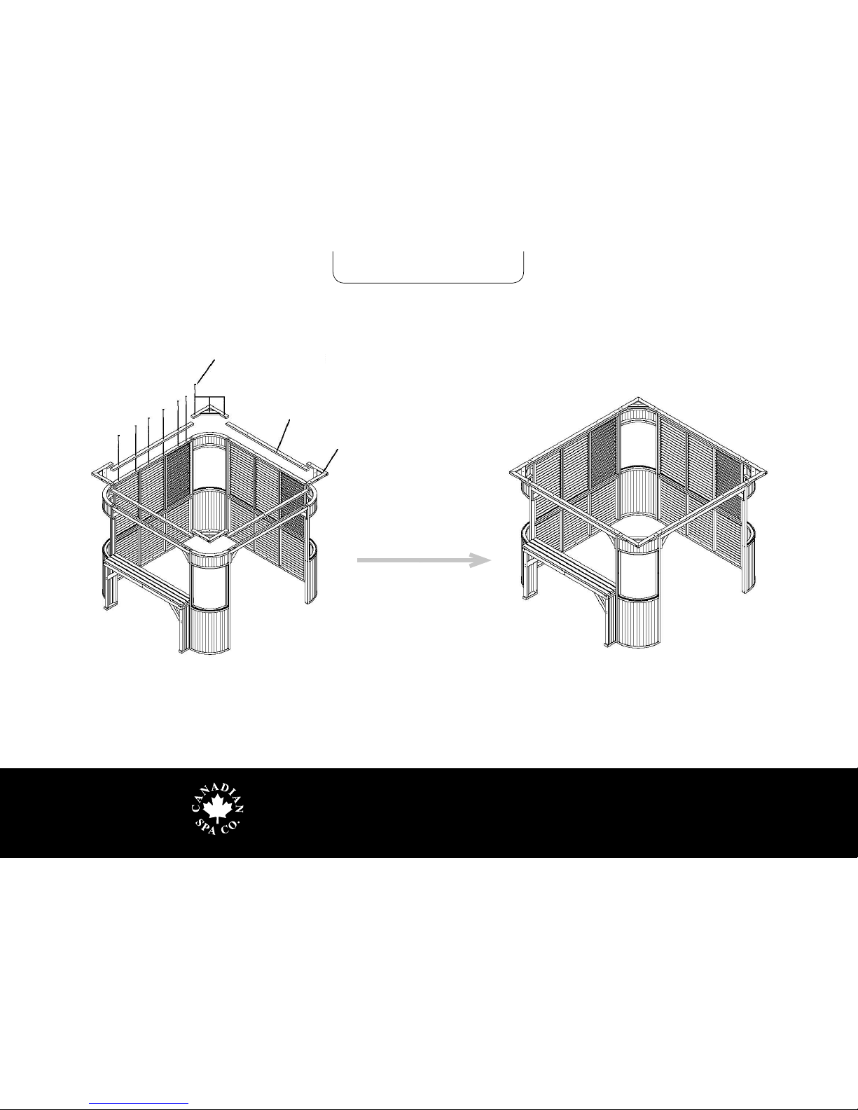
3. Wall corner(s) assembly
Tapping screw CT M5*50
1. Use Hexagon M8*50 bolts to connect corner C and louvred panels
2. Use Tapping screws CT M5*50 to connect the top and bottom panels
3. Use Hexagon M8*50 bolts to connect the second louvred
panel and gazebo corner.
4. Connect bar legs to gazebo corners using Hexagon M8*50 bolts
Hexagon bolt M8 * 50
Item No.
1
2
3
4
5
Quantity:
4 pcs
2 pcs
2 pcs
1 pc
2 pcs
40 pcs
12 pcs
Name:
Corner
Louvred window
Bottom panel
Bar table
Connecting beam
Hexagon bolt M8*50
Tapping screw CT M5*50
IMPORTANT: Please
ensure the gazebo walls and
corner units are square before
continuing to the next stage.
12
3
C
C
B
B5
4
B
C
D
A
Hexagon bolt M8 * 50
Hexagon bolt
M8 * 50
TIP: Leave lower wall
bolts loose until upper
louvred wall has been
installed. Then tighten
all bolts. This allows
for easier placement
of upper louvred
panels. 5
3
Fraser Gazebo - Assembly Instructions
www.canadianspacompany.com
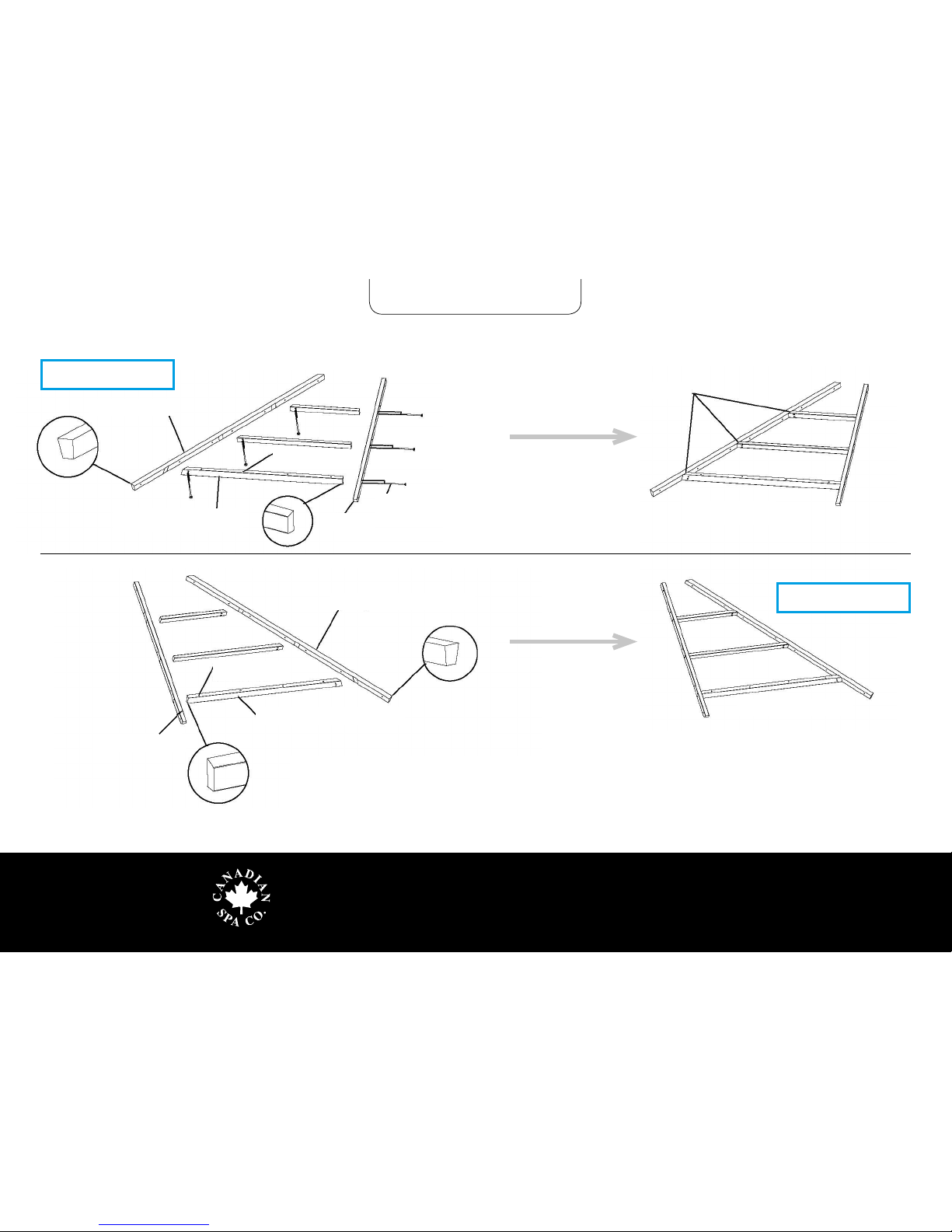
Tapping screw CT M5*50
Roof frame joist
Corner joist bracket
1. Link the 4 x Roof joists (1.97m) with corner joist brackets and
connect to Gazebo frame using Tapping screws (CT M5*50)
4. Roof frame joist(s) assembly
Fraser Gazebo - Assembly Instructions
www.canadianspacompany.com
Keep the contact surface at
Left Hip rafter (2A)
Roof crossmember (1A) Rafter (3A)
Ensure screw holes
face upwards
Tapping screw
CT M5*50
1. Roof (left hand-side):
1. Roof (left hand-side): Attach the long and short Roof crossmembers (1A) to the Left Hip Rafter (2A)
as well as Rafter (3A) using Tapping screws (CT M5*50).
2. Roof (right hand-side): Attach the long and short Roof crossmember (1B) to the Right Hip Rafter
(2B) as well as Rafter (3B) using Tapping screws (CT M5*50).
3. After the 3 x Roof crossmembers have been attached to the hip rafter lay the assembly at and lock
together with the screws
Ensure screw holes
face upwards
Right Hip (2B) Rafter 2. Roof (right hand-side):
Rafter (3 B)
Roof crossmember (1B)
5. Roof frame assembly

Fraser Gazebo - Assembly Instructions
www.canadianspacompany.com
M8*90 Bolts, Cap Nuts and Washers
Once the two frames have been assembled connect
them together using M8*90 Bolts, Cap Nuts and
Washers. Then place the rst roof frame on the
Gazebo body.
Roof frame
Gazebo body
IMPORTANT: Make sure the roof frame is level with
Gazebo body before screwing together.
Roof frame
6. Roof frame assembly
Andere Handbücher für Fraser
1
Inhaltsverzeichnis
Beliebte Außenlagerung Handbücher anderer Marken


Lifetime
Lifetime 6418 Bedienungsanleitung

rollaway container
rollaway container ARPCA24 Bedienungsanleitung

Duratuf
Duratuf Havelock Bedienungsanleitung

X-METAL
X-METAL 4065 Bedienungsanleitung

Outdoor Life Products
Outdoor Life Products FP2030 F Bedienungsanleitung

Royalcraft
Royalcraft Faro 295L Storage Box Bedienungsanleitung


