CASSENS & PLATH NETcourse Bedienungsanleitung

Installation & Operation Manual
Magnetic Compass Converter
CASSENS & PLATH GmbH
Manufacturers of Nautical Instruments
Am Lunedeich 131
D-27572 Bremerhaven, Germany
Tel. +49 471 483 999 0
Fax +49 471 483 999 10
www.cassens-plath.de
NETcourse

NETcourse
Page 2
Alterations/Errors reserved 15/Wo/251D
Cassens & Plath GmbH, Am Lunedeich 131, D-27572 Bremerhaven, Germany, tel. +49 471 483 999 0, fax +49 471 483 999 10
www.cassens-plath.de, [email protected]
Content
1) Drawings 3
- 1.1) Dimensions 3
- 1.2) Mounting of Control Unit 3
- 1.3) System Overview 4
- 1.4) Control Unit, Front Controls 5
- 1.5) Control Unit, Front Push Buttons 6
- 1.6) Control Unit , Rear 7
2) Menu-Mode 8
- 2.1) Menu “Load Default Errorlist” 8
- 2.2) Menu “Set Up Errorlist“ 8
- 2.3) Menu “Transmission Protocol“ 9
- 2.4) Menu “Detector Alignment” 9
3) Error Messages / Error Removing 10
4) Installation 11
- 4.1) Installation of Detector 11
- 4.2) Installation of Junction Box 12
- 4.3) Location of Detector and Junction Box within Compass Binnacle 12
5) Wiring 13
- 5.1) Power Supply 13
- 5.2) Connection of Junction Box 13
- 5.3) Connection of Data Output 13
- 5.4) Extension / Shortening of Detector Cable 14
6) Grounding 14
7) Start-up Operation 15
- 7.1) Check of Power Supply 15
- 7.2) Start Instrument and Check Operation 15
- 7.3) Check of Transmission Accuracy 15
8) Pin Connection of Plugs/Connectors 16
NETcourse
Page 3
Alterations/Errors reserved 15/Wo/251D
Cassens & Plath GmbH, Am Lunedeich 131, D-27572 Bremerhaven, Germany, tel. +49 471 483 999 0, fax +49 471 483 999 10
www.cassens-plath.de, [email protected]
1) Drawings
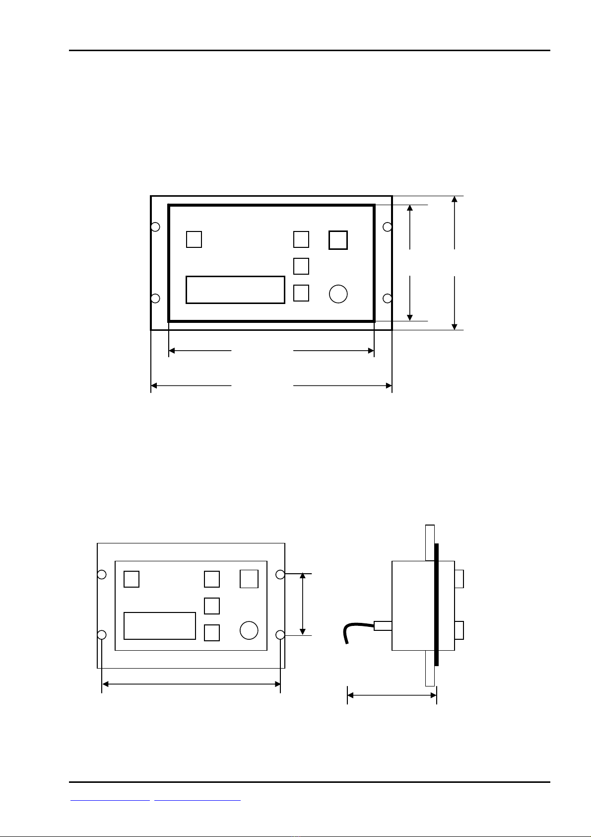
1.1) Dimensions
Flush mounting:
Weight: 2,1 KG
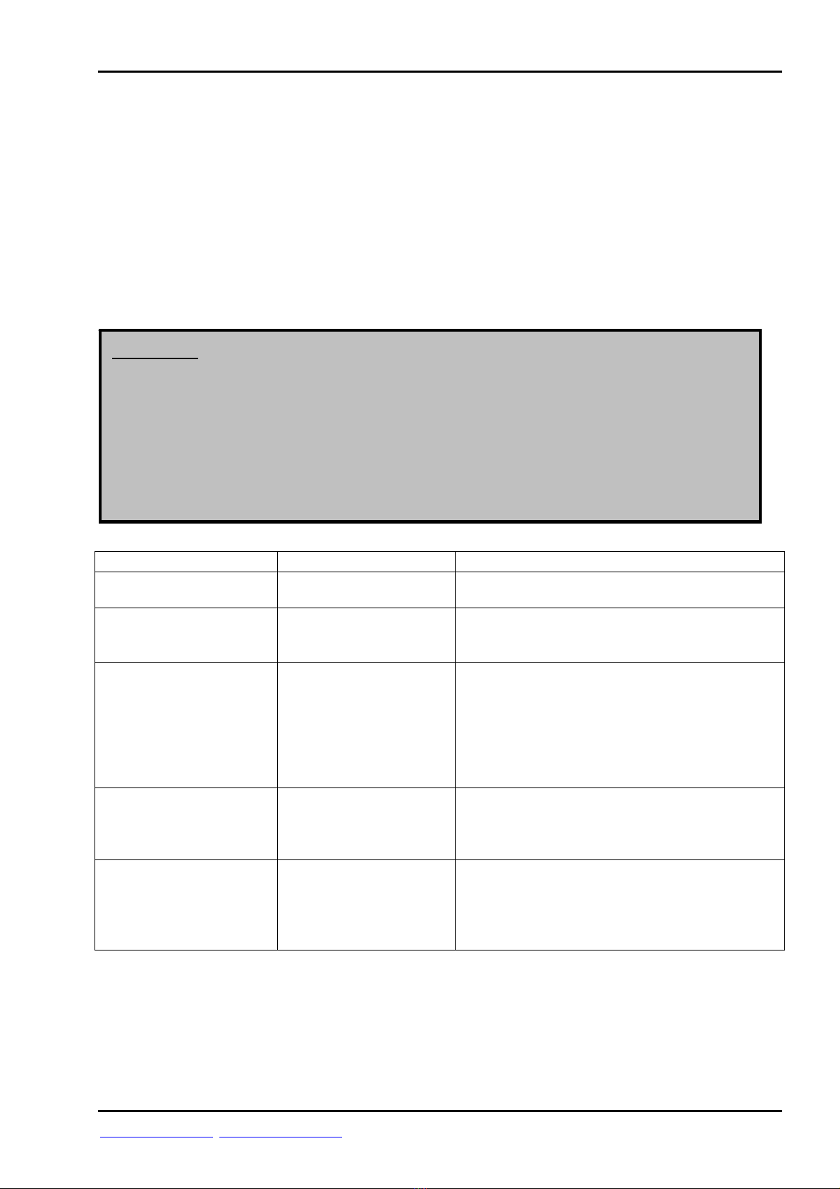
1.2) Mounting of Control Unit
Flush mounting (cut-out: 225 mm x 125 mm):
120 mm
220 mm
145 mm
245 mm
min. 110 mm
235 mm
85 mm

NETcourse
Page 4
Alterations/Errors reserved 15/Wo/251D
Cassens & Plath GmbH, Am Lunedeich 131, D-27572 Bremerhaven, Germany, tel. +49 471 483 999 0, fax +49 471 483 999 10
www.cassens-plath.de, [email protected]
1.3) System Overview
Compass
Mounting cylinder
Detector CP102B
Detector cable 1,5 m
(5-wires, screened)
with connector
Junction box
Detector cable 15 m
(5-wires, screened)
with connector
RS-485
Data output
with connector
Emergency power supply
24VDC, 4m (2-wires)
with connector
Main power supply
24VDC, 4m (2-wires)
with connecto
r
Control Unit

NETcourse
Page 5
Alterations/Errors reserved 15/Wo/251D
Cassens & Plath GmbH, Am Lunedeich 131, D-27572 Bremerhaven, Germany, tel. +49 471 483 999 0, fax +49 471 483 999 10
www.cassens-plath.de, [email protected]
1.4) Control Unit, Front Controls:
ERROR
1) LC-Display 2) On/Off switch 3) Dimmer
1) LC-Display shows actual functions, Menus or error messages
2) On/Off switch
3) Backlight dimmer of LC display

NETcourse
Page 6
Alterations/Errors reserved 15/Wo/251D
Cassens & Plath GmbH, Am Lunedeich 131, D-27572 Bremerhaven, Germany, tel. +49 471 483 999 0, fax +49 471 483 999 10
www.cassens-plath.de, [email protected]
1.5) Control Unit, Front Push Buttons:
“Back To Operation“ LC-Display “Enter” “Up/Down”
push botton push botton push bottons
“Back To Operation“ push botton Return to operation mode
“Up/Down” push botton Moves Menu one step up or down
“Enter“ push button Activates Menu mode,
Selects Menu
LC-Display Shows operation dialog
and error messages

NETcourse
Page 7
Alterations/Errors reserved 15/Wo/251D
Cassens & Plath GmbH, Am Lunedeich 131, D-27572 Bremerhaven, Germany, tel. +49 471 483 999 0, fax +49 471 483 999 10
www.cassens-plath.de, [email protected]
1.6) Control Unit, Rear
Grounding
Detector
RS-485 output
Emergency voltage
Main voltage

NETcourse
Page 8
Alterations/Errors reserved 15/Wo/251D
Cassens & Plath GmbH, Am Lunedeich 131, D-27572 Bremerhaven, Germany, tel. +49 471 483 999 0, fax +49 471 483 999 10
www.cassens-plath.de, [email protected]
2) Menu Mode
Press „Activate Menu/Enter“ to select.
Four Menus can be selected:
- “Load Default Error list“
- “Set Up Error list”
- “Transmission Protocol”
- “Detector Alignment”
Select required Menu by pushing “Up/Down“ push botton.
Press “Activate Menu/Enter“ to activate.
Press „Back To Operation“ to return to operation mode.
For safetey reasons NETcourse will return automatically to operation mode within two
minutes if no push botton was pressed, except Menu “Transmission Error“ was activated
before.
2.1) Menu Item “Load Default Error list“
By pressing “Load Default Error list“ the neutral or factoryside error table will be activated
and stored. The actual error table will be deleted!
Accept safety warning by striking “Menu/Enter“ button. Cancel by “Back To Operation“.
During restorage do not strike any further key!
2.2) Menu Item “Set Up Error list“
Adjust the traditional magnetic compass before correction of transmission error!
Transmission error is the difference of the direct reading of the magnetic compass and the heading
as displayed by NETcourse. This Menu item enables you to establish a errorlist. This is only
necessary in case too large transmission errors are recognized. These transmission errors are caused
by the direct interference of the corrector magnets to the detector, so these errors are not a
malfunction of the instrument but they result from the ship´s magnetic iron resp. their correction!
After activating this Menu item the display shows 0°, the first reference heading to establish
errorlist. Steer the ship into magnetic heading 0° (it is wrong to take out only the compass itself
from its suspension and rotate it into direction 0°). Accept this setting by “Menu/Enter“ push
button. The NETcourse display now proceeds to 15°. Steer the ship into magnetic heading 15° and
accept the setting same as above by actuating “Menu/Enter“ button. This way complete a total
swing of 360° for each reference heading of 15°. It is not necessary to follow each point of the
sequence of reference points. This Menu item also allows to select one of the reference headings
(0°, 15°, 30°, 45° ....) individually. To choose the required reference heading use the “Up/Down“
push button and activate setting by pushing „Menu/Enter“ button. It is not necessary to pass all
reference headings, each heading can be changed individually.

NETcourse
Page 9
Alterations/Errors reserved 15/Wo/251D
Cassens & Plath GmbH, Am Lunedeich 131, D-27572 Bremerhaven, Germany, tel. +49 471 483 999 0, fax +49 471 483 999 10
www.cassens-plath.de, [email protected]
2.3) Menu Item “Transmission Protocol“
With this menu item the data output protocol can be selected.
Two different sentence formats can be selected:
- $HCHDM,xxx.x,M*CS <CR> <LF>
- $HCHDG,xxx.x,,,,*CS <CR> <LF>
“xxx.x“ is the transmitted magnetic heading and “CS“ for the check sum.
Select the required sentence and data transmission parameters with “Up/Down“ and
activate with “Menu/Enter“.
“HCHDM,4800,1/s”
Sentence: Baud rate: Transmissions per second:
HCHDM 4800 1 transmission per second
HCHDG 38400 10 transmissions per second
30 transmissions per second
All transmissions are of 8 data bits, 1 stop bit and no parity.
2.4) Menu Item “Detector Alignment”
With this menu item the alignment of detector can be executed.
For installation of NETcourse it is necessary to align the detector to the magnetic
compass. For alignment loosen screws of detector a little bit, so that detector can be
turned slightly. Turn detector until displayed heading matches magnetic compass heading.
Fix the screws of detector.
NETcourse
Page 10
Alterations/Errors reserved 15/Wo/251D
Cassens & Plath GmbH, Am Lunedeich 131, D-27572 Bremerhaven, Germany, tel. +49 471 483 999 0, fax +49 471 483 999 10
www.cassens-plath.de, [email protected]
3) Error Messages/ Removing Errors
If from time to time error message “No Detector Input Data” appears, this can be caused
by an uncorrected heeling magnet of the compass.
So please check if at all corrections (deviation adjustment) were done. If not remove or
position heeling magnet as far as possible to the compass with detector. To find out how to
do this please refer to the relevant operations manual of the compass or compass
binnacle.
Error Reason Remedy
”Power Failure“,
Main- /Emergency
voltage below 18 VDC.
Make sure power supply : 24 VDC.
”Transmission Error“,
Transmission error table
not valid
Switch off and on instrument.
Carry out transmission error correction
procedure (ref. “Compass Reset“).
”No Detector Input
Data“,
Detector data not valid Make sure correct mounting of detector and
right distance to compass.
Make sure correct wiring of detector.
Make sure that there are no magnetic
interferences at detector location.
Check correct function of detector by use of a
multimeter *).
No function Switch on instrument.
Adjust dimmer to max. brightness to verify that
power is connected.
Make sure wiring and right voltage supply.
No data transmission.
NETcourse shows no
error message.
Make sure that data cables and connectors
are in order.
Interchange data cable A and B.
Make sure that correct output data
specification was selected.
*) Ref. to chapter „Pin Connection of Plugs/Connectors“
Measure resistance between:
Cosine und Reference: 60 Ohm, Sine und Reference: 60 Ohm, Sine und Cosine: 120 Ohm
Exitation 1 und Exitation 2: 50 Ohm, Exitation 1 or Exitation 2 and Reference: not connected
The values should be found within a tolerance of +/- 20%, else the detector might be defective.
Attention: The display shows existing operational errors and gives further
information. Please follow this information and refer to the error
shooting chapter of this operations manual. If the error cannot be
removed in this way switch off the instrument and call the
manufacturer.
Please pay attention to each error message carefully, else proper
operation cannot be guaranteed and safety of the vessel may be
endan
g
ered.
Inhaltsverzeichnis


