
Cedar HDA Bedienungsanleitung

Page 1
OWNER’S MANUAL
© 2009 CEDAR Audio Ltd
Manual version 1.00: August 2009
ADA converter
HDA headphone amplier

Page 2

Page 3
Table of Contents
Safety Instructions........................................................................................ 5
ADA: Introduction ......................................................................................... 6
ADA: Rear Panel Connections and Operation ............................................. 8
HDA: Introduction....................................................................................... 12
HDA: Rear Panel Connections and Controls.............................................. 13
HDA: Front Panel Connections and Operation .......................................... 14
CE Declaration of Conformity ..................................................................... 15
Specications - CEDAR ADA ..................................................................... 16
Specications - CEDAR HDA .................................................................... 17
Licence and Limited Warranty ................................................................... 18

Page 4

Page 5
SAFETY INSTRUCTIONS
Failure to adhere to the safety instructions may cause severe damage to an ADA or
HDA as well as risk of electric shock.
nUnpacking
Unpack the unit carefully. Save the packing materials since you may need
them to transport it in the future. In addition to this manual, the unit and its
packaging, the box should contain a mains lead, rubber feet, rackmounting
accessories and a warranty registration card.
nWater and moisture
The unit must not be exposed to rain or moisture. If it is brought directly
from a cold environment into a warm one, moisture may condense inside it.
Always allow it to reach ambient temperatures naturally before connecting
the mains power.
nInstallation site
To maintain reliability and prolong operating life, observe the following:
nthe temperature should be maintained between 5° and 30° Celsius
nrelative humidity should be in the range 30% to 80% non-condensing
nstrong magnetic elds should not exist nearby.
Do not subject the unit to strong sunlight, excessive dust, mechanical
vibration or periodic shocks. It is not susceptible to excessive heat build-
up, but should be installed away from heat sources such as radiators and
audio devices that produce large amounts of heat.
nMains voltage and Earthing (Grounding)
Before connecting to mains power, ensure that the voltage selector is set
to the correct voltage for the local mains supply, and that the fuse is of the
correct rating, as indicated on the rear panel. The unit must be earthed
to ensure a safe operating environment and to provide electromagnetic
shielding.
nConnections
Turn off the power to all equipment before making any connections.
nCleaning
Clean the unit only with a dry cloth. Never use abrasive pads or liquid
cleaners such as alcohol or benzene.
nDamage requiring service
The unit contains no user-serviceable parts and should not be opened by
unauthorised personnel. It should be returned to qualied service agents
when it has been exposed to liquids, when it fails to function correctly,
when it has been dropped, or when the case is damaged.

Page 6
ADA: INTRODUCTION
The CEDAR ADA is a 24-bit, 96kHz 1U rackmount unit that produces an AES/EBU
or SPDIF digital audio output from a balanced or unbalanced analogue stereo
audio input. It also produces a stereo balanced or unbalanced analogue output
from an incoming AES/EBU or SPDIF digital input signal.
At any given time, the unit operates in one of four sync modes:
Master Mode
The clock signals are generated internally by an on-board master clock at a user-
selectable rate: 32kHz, 44.1kHz, 48kHz, 64kHz, 88.2kHz or 96kHz.
Slave Mode
If a digital signal is present at the selected digital input, the ADA synchronises to it.
If no such signal is present, no output is generated.
Auto Mode
If a digital signal is present at the selected digital input, the ADA synchronises to
it. If no such signal is present, the ADA uses its internal master clock at the user-
selected sample rate.
Auto Lock Mode
This operates in the same manner as Auto Mode except that, if no digital signal
is present, the ADA uses its internal master clock running at the most recently
synchronised sample rate.
When operating in any other than Master Mode, the front panel power LED will
ash whenever the ADA is not synchronised to an incoming digital signal.

Page 7
Input and Output
The CEDAR ADA has analogue inputs and outputs at both professional and
consumer signal levels. The professional level signals are electronically balanced
and use XLR connectors, while the consumer signals are unbalanced and are
carried by RCA (phono) connectors. In each case, the input level is adjustable
over a range of 18dB, and the output level may be set to one of three levels, each
separated by 6dB.
There is a button to select professional or consumer input. Both outputs are active
at all times. There are also buttons to select the AES/EBU or SPDIF input or output
for the D/A and A/D sections.
You may dene the channel status bits embedded within the digital audio.
For sample rates of 32kHz, 44.1kHz and 48kHz, the status bits can be set to
Professional or Consumer mode. For sample rates above 48kHz, the status bits
will be forced to Professional mode because the ADA does not support Consumer
mode at these rates.
Front Panel LED
The LED on the front panel is normally lit to indicate that power is present. Flashing
indicates either (i) a loss of digital input or (ii) that the unit is being calibrated.
Block Diagram
Gain
Digital Send
Select
ADC
AES
Tr ansmitter
Digital Source
Select
AES
Receiver
Frequency
Select
Master
Clock
Generator
Digital Input
AES/EBU
SPDIF
DAC
L
L
L
L
R
R
R
R
Consumer
Unbalanced
Digital Output
Analogue Output
Consumer
Unbalanced
Professional
Balanced
Recovered
Clock
Professional
Balanced
Analogue Input
Select
Analogue InputGain
AES/EBU
SPDIF
Page 8
ADA: REAR PANEL CONNECTIONS AND
OPERATION
Inputs
XLR Analogue Inputs (Left and Right)
The XLR 3-pin sockets used for the analogue left and right channel inputs are
electronically balanced and have an impedance of greater than 10kΩbridging.
Each XLR has the following connections:
nPin 1: Screen.
nPin 2: Signal +ve (hot)
nPin 3: Signal -ve (cold)
RCA Phono Inputs (Left and Right)
The left and right RCA (phono) analogue inputs are unbalanced and have an
impedance of greater than 20kΩ.
Input Level Adjustment
The input gain can be adjusted individually for the left and right channels using
the DIP switches and the preset potentiometers accessible on the rear panel. The
input gain can be set such that signals of +12, +18 or +24dBu generate full-scale
signals in the digital domain. Individual preset controls provide a further ± 3dB to
give an input level range of +9dBu to +27dBu.
The consumer input on the phono connector has a further gain of 10dB to provide
an input level range of -1dBu to +17dBu.
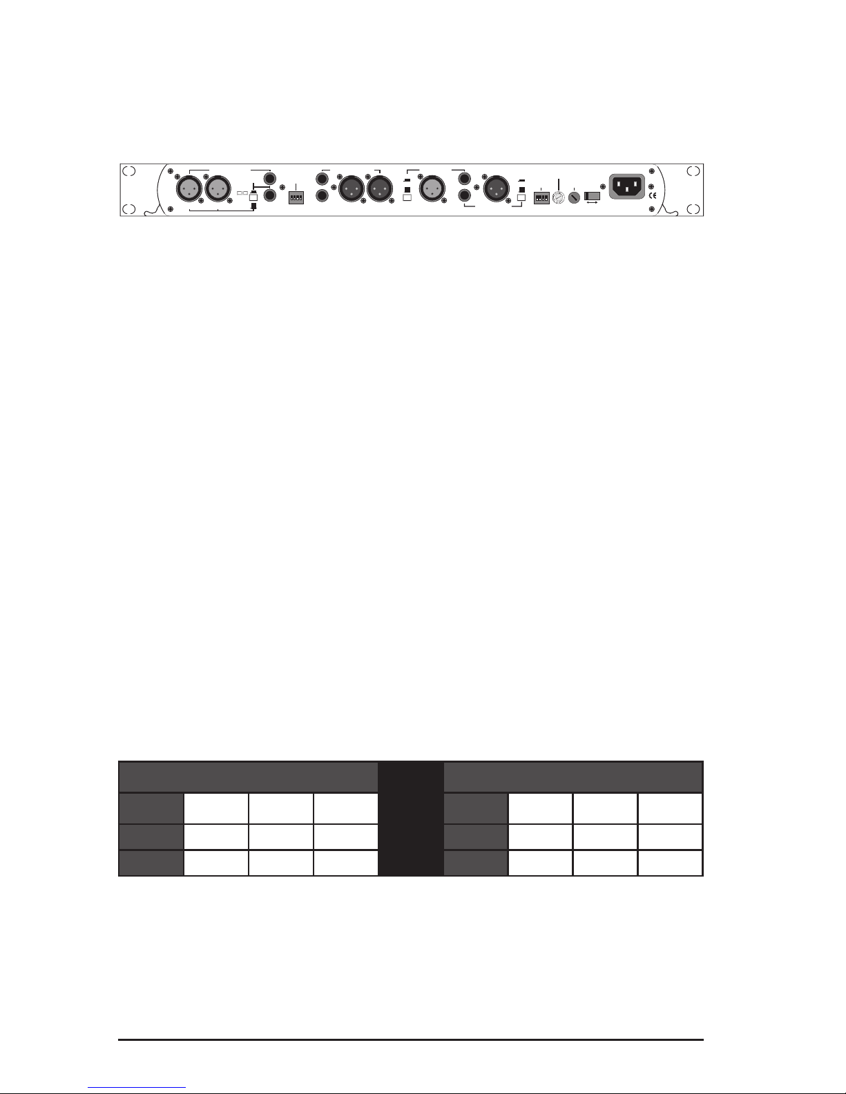
Input Level Settings (dB) Output Level Settings (dB)
Switch +12 +18 +24 Switch +12 +18 +24
1OFF ON ON 3OFF ON ON
2OFF OFF ON 4OFF OFF ON
S/PDIF
AES/EBU
ANALOGUE INPUTS ANALOGUE OUTPUTS
L R
LEVEL
CAUTION
:
Disconnect the mains supply before removing the equipment covers.
DIGITAL OUTPUTSRIGHTLEFT
R
FREQUENCIES
AND SYNC
MODES
230V 100mA
115V 200mA
FUSE
CEDAR ADA CONVERTER
L
DIGITAL INPUTS
RIGHT
S/PDIF
LEFT
This product must be earthed
AES/EBU
AES/EBU OUTPUT
AES/EBU INPUT
L
R
STATUS
FULL SCALE
dB SETTINGS
INPUT
SELECT
115V - 230V

Page 9
AES/EBU Input
The digital input XLR 3-pin socket has an impedance of 110Ω. It has the following
connections:
nPin 1: Screen.
nPin 2: Signal +ve (hot)
nPin 3: Signal -ve (cold)
SPDIF Input
The SPDIF input has an impedance of 75Ω.
Outputs
Analogue Outputs (Left and Right)
The XLR 3-pin output connectors are electronically balanced with an output
impedance of less than 50Ω. They have the following connections :
nPin 1: Screen.
nPin 2: Signal +ve (hot)
nPin 3: Signal -ve (cold)
RCA phono Outputs (Left and Right)
The RCA (phono) outputs are unbalanced and have an output impedance of less
than 75Ω.
Output Level Adjustment
The output gain can be adjusted individually for the left and right channels
using the rear panel DIP switches. Each output gain can be set such that a full-
scale digital output provides +12, +18 or +24dBu output on the analogue XLR
connectors.
The level at the unbalanced output is 10dB lower than at the balanced output.
AES/EBU Output
The digital output XLR 3-pin socket has an impedance of 110Ω, and output signals
comply with IEC 60958. The socket has the following connections:
nPin 1: Screen.
nPin 2: Signal +ve (hot)
nPin 3: Signal -ve (cold)
SPDIF Output
The SPDIF output has an impedance of 75Ω.

Page 10
Rear Panel Controls
Status Select Switches
These switches determine the channel status of the digital signals.
The channel status bits of the digital audio signal can be Professional or Consumer,
as determined by switch 1. At sample rates higher than 48kHz, Consumer mode is
not available, so Professional mode is used and this switch is ignored.
If de-emphasis is selected (switch 2) the ADA will decode 50/15µs emphasis when
the incoming channel status indicates that this is appropriate.
The wordlength for the A/D conversion can be set to 24, 20 or 16 bits. When the
signal is truncated from 24 bits, a psychoacoustic lter is applied to maintain
optimum signal quality.
These settings are summarised by the following tables:
Switch Status Meaning
1 ON PROFESSIONAL
1 OFF CONSUMER
2 ON DE-EMPHASIS AUTO
2 OFF DE-EMPHASIS OFF
Switch Wordlength
16-bit 20-bit 24-bit
3 OFF OFF ON
4 OFF ON ON
All current CEDAR digital processors are 24-bit, so we advise you to leave the
wordlength at 24 bits.
Digital Select Buttons
These buttons allow you to switch between AES/EBU (button out) and SPDIF
(button in) for each of the digital input and output.
Analogue Select Button
This button switches the analogue input between the balanced (button out) and the
unbalanced (button in) connectors.
Dieses Handbuch passt für folgende Modelle
1
Inhaltsverzeichnis


