
Chauvin Arnoux E27 Bedienungsanleitung

AC/DC current clamp
EN - User’s manual
E27

2
WARNING, risk of DANGER! The operator must refer to this user’s manual whenever this danger symbol appears.
May be placed on and removed from conductors at dangerous voltages. Type A current sensor as per IEC 61010-2-032.
Equipment protected by double insulation. Battery.
Useful information or tip. USB.
To identify the phase (or the direction) of the primary current.
Chauvin Arnoux has adopted an Eco-Design approach in order to design this appliance. Analysis of the complete life-
exceeds regulation requirements with respect to recycling and reuse.
The CE marking indicates compliance with the European Low Voltage Directive, 2014/35/UE, the Electromagnetic
Compatibility Directive, 2014/30/EU, and the Restriction of Hazardous Substances Directive, (RoHS 2011/65/UE and
2015/863/UE).
The rubbish bin with a line through it indicates that, in the European Union, the product must undergo selective disposal
in compliance with Directive WEEE 2012/19/UE: This equipment must not be treated as household waste.
Thank you for purchasing an E27 AC/DC current clamp, which we trust will give you satisfaction.
For best results from your instrument:
read this user manual carefully,
comply with the precautions for use.
Denition of measurement categories
Measurement category IV corresponds to measurements taken at the source of low-voltage installations.
Example: power feeders, counters and protection devices.
Measurement category III corresponds to measurements on building installations.
Measurement category II corresponds to measurements taken on circuits directly connected to low-voltage installations.
Example: power supply to domestic electrical appliances and portable tools.
PRECAUTIONS FOR USE
This device is compliant with safety standard IEC 61010-2-032, for voltages up to 600V in category III or 300 V in category IV.
installations.
The operator and/or the responsible authority must carefully read and clearly understand the various precautions to be taken in
use. Sound knowledge and a keen awareness of electrical hazards are essential when using this instrument.
Do not use the instrument on networks of which the voltage or category exceeds those mentioned.
Do not use the instrument if it seems to be damaged, incomplete, or poorly closed.
Before each use, check the condition of the insulation on the leads and housing. Any item of which the insulation is deteriorated
(even partially) must be set aside for repair or scrapping.
Do not expose the clamp to sprays of water.
Use personal protection equipment systematically.
All troubleshooting and metrological checks must be done by competent, accredited personnel.

3
CONTENTS
1. PRESENTATION ..................................................................................................................................................................... 4
1.1. Delivery condition ........................................................................................................................................................... 4
1.2. Accessories .................................................................................................................................................................... 4
1.3. Inserting the battery........................................................................................................................................................ 4
1.4. Functions ........................................................................................................................................................................ 4
1.5. E27 clamp....................................................................................................................................................................... 5
2. USE........................................................................................................................................................................................... 6
2.1. Getting started ................................................................................................................................................................ 6
2.2. Zero adjustment.............................................................................................................................................................. 6
2.3. Measurement.................................................................................................................................................................. 6
........................................................................................................................................................................... 7
2.5. Indicators ........................................................................................................................................................................ 7
2.6. Mains adapter (option).................................................................................................................................................... 7
3. SPECIFICATIONS................................................................................................................................................................... 8
3.1. Reference conditions...................................................................................................................................................... 8
3.2. Electrical characteristics ................................................................................................................................................. 8
3.3. Operating limits............................................................................................................................................................. 12
3.4. Variations in the range of use ....................................................................................................................................... 12
3.5. Power supply ................................................................................................................................................................ 12
3.6. Environmental conditions ............................................................................................................................................. 13
........................................................................................................................................... 13
3.8. Conformity to international standards........................................................................................................................... 14
3.9. Electromagnetic compatibility ....................................................................................................................................... 14
4. MAINTENANCE..................................................................................................................................................................... 15
4.1. Cleaning ....................................................................................................................................................................... 15
4.2. Replacing the battery.................................................................................................................................................... 15
4.3. Manual adjustment ....................................................................................................................................................... 15
5. WARRANTY........................................................................................................................................................................... 17

4
1. PRESENTATION
1.1. DELIVERY CONDITION
The E27 clamp is delivered in a cardboard box with:
one 9V alkaline battery (type 6LR61 or NEDA 1604A),
one multilingual getting started guide,
one multilingual safety data sheet,
1.2. ACCESSORIES
One 5V, 500mA external power supply comprising:
one mains/USB type A adapter
one USB type A/micro-USB type B cable
For the accessories and spares, consult our web site:
www.chauvin-arnoux.com
1.3. INSERTING THE BATTERY
Use a screwdriver to unscrew the captive screw of the battery compartment cover.
Connect the battery to the snap-on connector; take care with the polarity.
You can use a rechargeable Ni-MH battery, but the life will be shorter. The instrument does not recharge rechargeable batteries.
Place the battery in its compartment.
Put the battery compartment cover back in place; make sure that it is completely and correctly closed.
Screw the screw back in.
1.4. FUNCTIONS
The E27 clamp can be used to measure current from 100mA to 100 Apeak
out the waveform and amplitude of the current being measured, in the form of a voltage. The pass band is from DC to 100kHz.
The shape of the clamp enables it to reach hard-to-reach places.
This clamp is used with an oscilloscope.
It can be powered by a battery or at 5VDC via the micro-USB connector.
It has:
a reset pushbutton,
a range overshoot indicator,
a power supply indicator,
automatic standby to prolong battery life.
➀➁
➂
➄
➃

5
1.5. E27 CLAMP
I
Zéro
600 V CAT III
P
ON
AUTO POWER OFF
OL
100 mV/A
10 mV/A
OFF
Mobile jaw.
Fixed jaw.
Guard
Reset button.
ON and OL indicators.
Three-position slide
switch.
Type B micro-USB con-
nector.
Mobile arm.
Battery compart-
ment cover.
Screw of the battery
compartment cover.
Fixed arm.
Male BNC connector.

6
2. USE
2.1. GETTING STARTED
Switch the clamp on by pushing the slide switch to the 10mV/A or the 100mV/A setting.
The 10mV/A setting corresponds to the 100A range.
The 100mV/A setting corresponds to the 10A range.
The ON indicator lights green. If it blinks, there remain less than 4 hours of use. If it fails to light, you must replace the battery (see
§ 4.2).
It takes 10 seconds to set the clamp up for use.
2.2. ZERO ADJUSTMENT
Switch the clamp on.
Connect the clamp to the measuring instrument. The phase is on the core of the BNC connector.
Make sure that the clamp is not on a conductor and that its jaws are correctly closed.
Place the clamp in the position it will be in during the measurement.
Press the zero adjustment button.
The OL indicator lights for approximately three seconds to indicate that the zero adjustment is in progress in the two ranges.
If the zero has been correctly adjusted, the OL
In this case, check that the clamp is not on any conductor and that its jaws are correctly closed, then press the zero adjustment
button again.
2.3. MEASUREMENT
The zero must be adjusted before each measurement.
Once the zero has been adjusted, press the moving arm of the clamp to open the jaws.
Clamp the cable carrying the current to be measured. Use the centring marks to help you centre the cable inside the jaws of
the clamp.
producer consumer
source load
I
I
I
Release the moving arm gently and make sure that the jaws are correctly closed.
The value measured is displayed on the measuring instrument.

7
If the OL indicator lights, it means that the current is too strong to be measured. If you are in the 100mV/A range, switch to the
10mV/A range.
Apply the conversion factor corresponding to the setting of the switch.
I
I = = 5 A
500 mV
100 mV/A
COM +
mV
mV
100 mV/A
10 mV/A
OFF
Range 100 A 10 mV/A
Range 10 A 100 mV/A
2.4. AUTO OFF
At the end of 10 minutes of operation with no sign of the user’s presence (a press on the zero adjustment button or an action on
the switch), the clamp switches to standby and the ON
To wake up the clamp, press the zero adjustment button or set the switch to a position other than OFF.
P), press the zero adjustment button when starting up the instrument. The
ON indicator blinks to indicate that the request has been taken into account, then lights steady orange when you release the zero
adjustment button.
OFF
2.5. INDICATORS
ON indicator OL indicator
Lighted green: instrument on Lighted red: The measurement exceeds the range
Blinking green: the batteries will have to be replaced
in less than 4h 3 s
Lighted red for 3 seconds: the zero adjustment is in
progress.
Lighted orange: permanent operation P
deactivated)
2.6. MAINS ADAPTER (OPTION)
For long-term measurements, you can connect the clamp to mains using the optional line power adapter. You can use any mains/
micro-USB adapter that delivers 50mA or more.
When the instrument is powered via the micro-USB connector, automatic standby is disabled.
The insulation between the type B micro-USB connector and the measurement output is 600V CAT III. This makes it possible to
connect the clamp, without risk, to measuring instruments having inputs that are not insulated. The type B micro-USB connector
must not be in contact with conductors or uninsulated parts at dangerous voltage.
If the external power supply is disconnected, the clamp changes back to battery-powered operation. The colour of the ON indicator
indicates whether automatic standby is enabled (indicator green) or not (indicator orange).

8
3. SPECIFICATIONS
3.1. REFERENCE CONDITIONS
Quantity of inuence Reference values
Temperature 23 ± 5 °C
Relative humidity 20 to 75%RH
Position of the conductor centred
Frequency of the measured signal DC to 65 Hz sine wave
Powered by battery: 6.5 to 9 V
external supply: 5 V ± 0.1 V
zero
< 40 A/m
zero
Impedance of the measuring instrument
The intrinsic uncertainty
± (a% R + b)
3.2. ELECTRICAL CHARACTERISTICS
Range 100mV/A (10A) 10mV/A (100A)
0.1 to 10 Apeak 0.5 to 40 Apeak 40 to 100 Apeak
Intrinsic uncertainty
Phase shift (DC to 65Hz)
3.2.1. TYPICAL CURVES
Typical amplitude error curve for a DC current, 10mV/A range
-18,00
-16,00
-14,00
-12,00
-10,00
-8,00
-6,00
-4,00
-2,00
0,00
2,00
4,00
6,00
8,00
10,00
12,00
110 100
Error (%)
Maximum envelope
Minimum envelope
Current (A)

9
Typical amplitude error curve for a 60Hz AC current, 10mV/A range
Error (%)
-18,00
-16,00
-14,00
-12,00
-10,00
-8,00
-6,00
-4,00
-2,00
0,00
2,00
4,00
6,00
8,00
10,00
12,00
14,00
16,00
18,00
110 100 Current (A)
3.2.2. NOISE
Typical noise level at output
10mV/A range ± 600 µVpeak to peak
1V/A range ± 5 mVpeak to peak
3.2.3. ZERO ADJUSTMENT
Minimum zero adjustment range: ± 1 A in steps of approximately 0.9 mA.
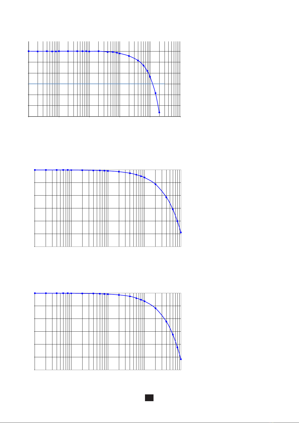
3.2.4. FREQUENCY RESPONSE
Typical amplitude error curve at 1 A versus frequency, 10mV/A range
Error (%)
-6dB
-5dB
-4dB
-3dB
-2dB
-1dB
0dB
10 100 1000 10000 100000 1000000 Frequency (Hz)
10
-6dB
-5dB
-4dB
-3dB
-2dB
-1dB
0dB
1dB
10 100 1000 10000 100000 1000000
-120,00
-100,00
-80,00
-60,00
-40,00
-20,00
0,00
10 100 1000 10000 100000
-120,00
-100,00
-80,00
-60,00
-40,00
-20,00
0,00
10 100 1000 10000 100000
Typical amplitude error curve at 1A versus frequency, 100mV/A range
Error (%)
Frequency (Hz)
Typical amplitude error curve as a function of frequency, I = 1A, 10mV/A range
Phase shift (°)
Frequency (Hz)
Typical amplitude error curve as a function of frequency, I = 1A, 100mV/A range
Phase shift (°)
Frequency (Hz)
Andere Handbücher für E27
1
Inhaltsverzeichnis
Andere Chauvin Arnoux Werkzeuge Handbücher


