CHUNDA ISCDOSA4205 Bedienungsanleitung

ISCDOSA4205
Standalone Access Controller
Hardware Manual
Version 1.0

CHUNDA 2 ISCDOSA4205 Hardware manual
Table of Contents
Chapter 1 Product Overview...............................................................................................4
1.1 Package Contents..................................................................................................4
1.2 Features.................................................................................................................5
1.3 Specifications.........................................................................................................6
Chapter 2 Physical Dimension............................................................................................7
2.1 Dimension..............................................................................................................7
2.2 Appearance Introduction........................................................................................8
Chapter 3 System Configuration & Wire Connections.........................................................9
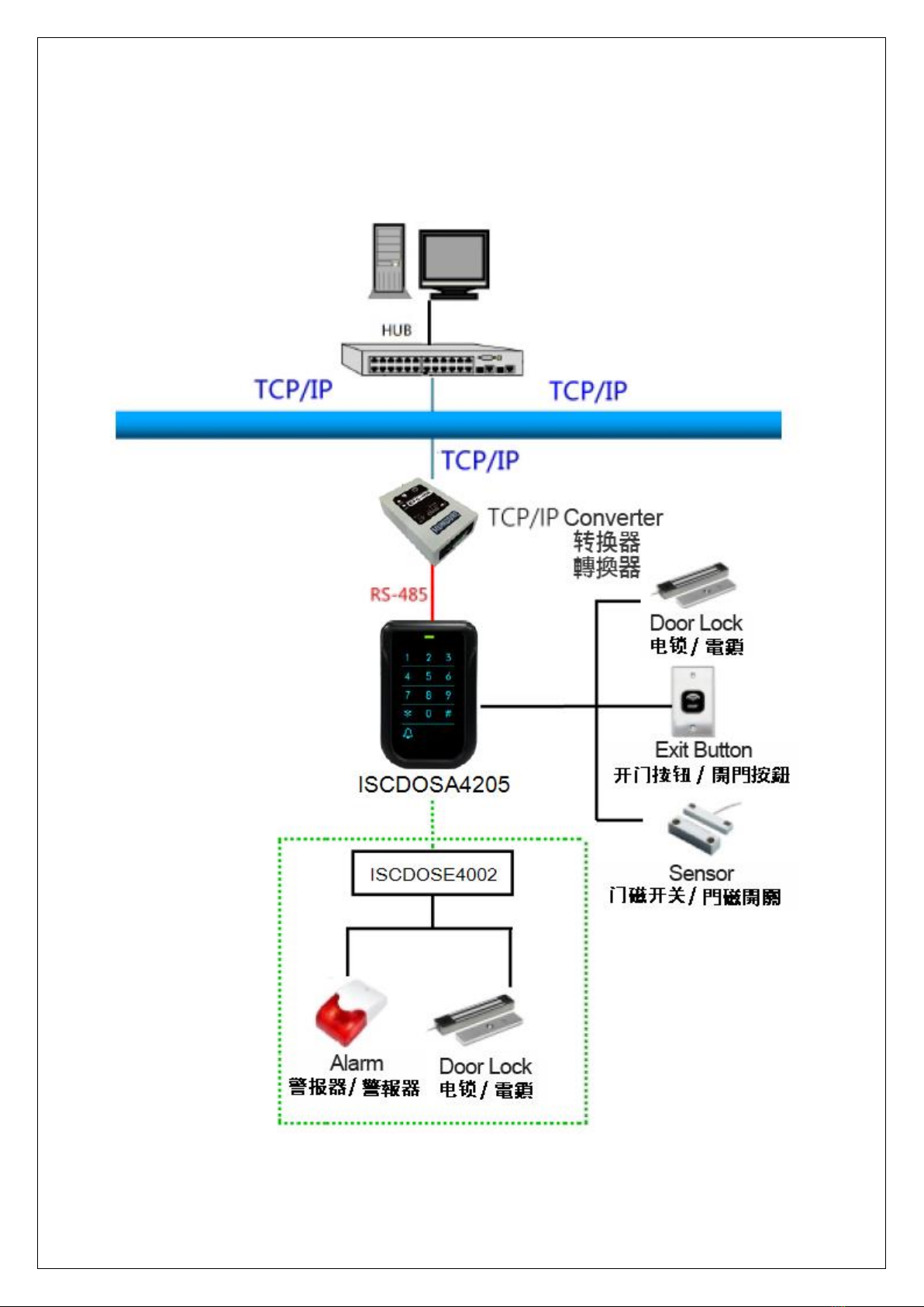
3.1 System Configuration.............................................................................................9
3.2 Wire Connections.................................................................................................10
3.2.1 Controller Terminal Introduction.................................................................10
3.2.2 Alarm Connection ......................................................................................11
3.2.3 Electronic Lock Setup ................................................................................12
3.2.4 Exit Button/Door Sensor Connection .........................................................13
3.2.5 Slave Reader Connection..........................................................................15
3.2.6 Power Supply Connection..........................................................................16
Chapter 4 Installations ......................................................................................................17
4.1 Hardware Setup...................................................................................................17
4.2 Communication Interface Connection..................................................................18
4.3 ISCDOSE4002 Wire Diagram..............................................................................19
Chapter 5 Setting..............................................................................................................20
5.1 ID Setting.............................................................................................................20
5.2 Function Settings .................................................................................................21
5.2.1 Add a Card Number...................................................................................22
5.2.2 Delete a Card Number...............................................................................23
5.2.3 Delete All Card Numbers ...........................................................................24
5.2.4 Successive Addition of Card Numbers.......................................................25
5.2.5 Successive Deletion of Card Numbers ......................................................26
5.2.6 Set Door Relay Mode.................................................................................27
5.2.7 Set Unlock Door Time................................................................................28
5.2.8 Door Sensor Detection Time......................................................................29
5.2.9 Enable/Disable Conditional Unlock Door Settings .....................................30
5.2.10 Compare valid Address............................................................................31
5.2.11 Advanced Settings 1................................................................................32

CHUNDA 3 ISCDOSA4205 Hardware manual
5.2.12 Advanced Settings 2................................................................................33
5.2.13 Reswipe Card Check Time ......................................................................34
5.2.14 Sensor NO/NC Settings...........................................................................35
5.2.15 Access Granted for Master Code.............................................................36
5.2.16 Set Date...................................................................................................37
5.2.17 Set Time...................................................................................................38
5.2.18 Enable/Disable Keypad............................................................................39
5.2.19 Save Invalid Card No...............................................................................40
5.2.20 Mifare Card Reading Format....................................................................41
5.2.21 Mifare Read Block Settings......................................................................42
5.2.22 Mifare Index of card No............................................................................43
5.2.23 Mifare Length of card No..........................................................................44
5.2.24 Compress Mifare Card No. ......................................................................45
5.2.25 Set Key Value..........................................................................................46
5.2.26 Read Block Mode.....................................................................................47
5.2.27 Set Master Code......................................................................................48
5.2.28 Set Disarm Card/Code.............................................................................49
5.2.29 Set Duress Card (Code)...........................................................................50
5.2.30 Set Memory Mode....................................................................................51
5.2.31 Door Open Mode .....................................................................................52
5.2.32 Valid Card Mode......................................................................................53
5.2.33 Slave Reader Setting...............................................................................54
5.2.34 Relay Mode..............................................................................................55
5.2.35 System Initialization .................................................................................56
Chapter 6 Testing..............................................................................................................57
Chapter 7 Troubleshoot ....................................................................................................58
Appendix...........................................................................................................................59
Appendix A:ISCDOSA4205 Function List................................................................59
Appendix B:Wiring Material Requirements..............................................................63
Revision History
Version
Description
V1.0
First Edition

CHUNDA 4 ISCDOSA4205 Hardware manual
Chapter 1 Product Overview
1.1 Package Contents
Controller x 1
Base x 1
Quick Start Guide x 1
Screw x 3
Cable x 1

CHUNDA 5 ISCDOSA4205 Hardware manual
1.2 Features
Supports standalone operation; provides function keys to add or delete users’
password and card number.
Supports entry modes through card-swiping or card-swiping with password for high
security.
Slim, stylish design, capacitive touch keypad with blue backlight, suits for various
locations.
With a doorbell key for connecting external doorbell device.
Conforms to ISO 14443A, supporting Mifare card.
Unique ID or Block reading format supported and programmable key value.
Duress card / code setting. When door opened in the emergency, controller will send
signal to control center at the same time for tracing and rescue.
Supports door ajar alarm.
Casing tamper proof detection can set the auxiliary relay to activate the relevant
alarm device.
Wide operation temperature range, it can be install in different arctic or tropical
regions.
Provides RS-485 communication interface for long distance installation.
Watchdog function secures system free from halting.

CHUNDA 6 ISCDOSA4205 Hardware manual
1.3 Specifications
* Product design and specifications are subject to change without prior notice.
Model No.
ISCDOSA4205
Cardholders
1,024
Events
800
Read Format
Mifare (13.56MHz )
Read Range
3-5 cm (max)
Comm. Interface
RS-485
Input Ports
3 Sensors (Door Sensor x 1、Exit switch x 1、Tamper
Switch x 1)
Output Ports()
Built-in Relay x 1 (Door Lock or Bell), O.C. Output x 2
(Door Lock/Alarm, external ISCDOSE4002)
Keypad
13 Key (0-9, *, #, Bell) (Sensitive Touch Keypad)
ID Setting
DIP switch setting
Comm. Baud Rate
19,200 bps
LED Indicator
Comm.
Beep Tone
Buzzer
Power Input
DC 12V / 1A
Current Consumption
250mA (max.)
Operating Temp.
-20℃~ 70℃/ -4℉~ 158℉
Relative Humidity
20% ~ 80%
Dimension
120mm(L) x 80mm(W) x 28mm(H)

CHUNDA 7 ISCDOSA4205 Hardware manual
Chapter 2 Physical Dimension
2.1 Dimension
Scale:mm

CHUNDA 8 ISCDOSA4205 Hardware manual
2.2 Appearance Introduction
Item
Name
Description
A
POWER
Power LED, flashed green led usually
B
Numerical
Keypad
0~9: Numeric key. *: Cancel #: Enter
C
Bell
Bell Function key
Request Bell function should select mode 1 and activate by
HAMS.
Relay Active as below
(Relay 0 signifies Controller relay. Relay 1~2 signifies relay in
the external relay board.)
Relay0
Relay1
Relay2
Relay3
Mode 0
Door
Door
Alarm
X
Mode 1
Bell
Door
Alarm
X

CHUNDA 9 ISCDOSA4205 Hardware manual
Chapter 3 System Configuration & Wire Connections
3.1 System Configuration

CHUNDA 10 ISCDOSA4205 Hardware manual
3.2 Wire Connections
3.2.1 Controller Terminal Introduction
A
Case Sensor
B
IDSetting (Kindly refer to Chapter5.1)
C
Contact( (Kindly refer to Chapter 3.2)
D
JP1 Built in Relay
Inhaltsverzeichnis


