Cistermiser sensazone SZ/IF Bedienungsanleitung

sensazone
installation guide
sensazone is an intelligent PIR sensor operated system which controls
the water supply and the light and fan functions in washrooms.
The system features can be used in the following scenarios
Scenario Required control Required products
1To control the water supply to one zone, room or area
of a washroom (with a single/common entrance).
sensazone core product
2
To control the water supply and lights and fans to
one zone, room or area of a washroom (with a single/
common entrance).
sensazone core product
A sensazone Interface Module
A sensazone Light and Fan Control
3
To control the water supply to multiple areas of a
washroom simultaneously. Examples include, a
washroom divided into different areas and a washroom
with two or more entrances.
sensazone core product
A sensazone Interface Module
Additional Sensor Kits
Additional Valve Kits
(where applicable, to a maximum of 3 valves per system)
4
To control the water supply, lights and fans to multiple
areas of a washroom (with two or more entrances).
sensazone core product
A sensazone Interface Module
A sensazone Light and Fan Control
Additional Sensor Kits
Additional Valve Kits
(where applicable, to a maximum of 3 valves per system)
1 System requirements
1
0118 969 1611 | sales@cistermiser.co.uk | www.cistermiser.co.uk
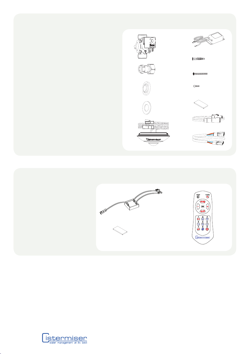
sensazone core - supplied parts
sensazone Interface Module (SZ/IF) - supplied parts
1 Solenoid valve**
2 2 x 22mm compression fittings*
3 Inlet filter*
4 Fibre washer*
5 Sensor assembly consisting of sensor
unit and backplate
6 Mains power adaptor
7 2 x universal fixing plug
8 2 x #6 x 1 1/2” screws
9 4 x #4 x 1/2” screws
10 4 x sticky pads
11 Extension cable to mains power adaptor
(1.25m)
12 Extension cable to solenoid valve (3m)
1 sensazone Interface module
2 Sticky Pads x 2
3 Infrared Control Unit (ICU)
1**
1
** Solenoid valve either 15mm, 22mm, 1” or 11/4”
* Only supplied with 15mm or 22mm
2*
2
3*
4*
5
6
7
8
9
10
11
12
3
20118 969 1611 | sales@cistermiser.co.uk | www.cistermiser.co.uk
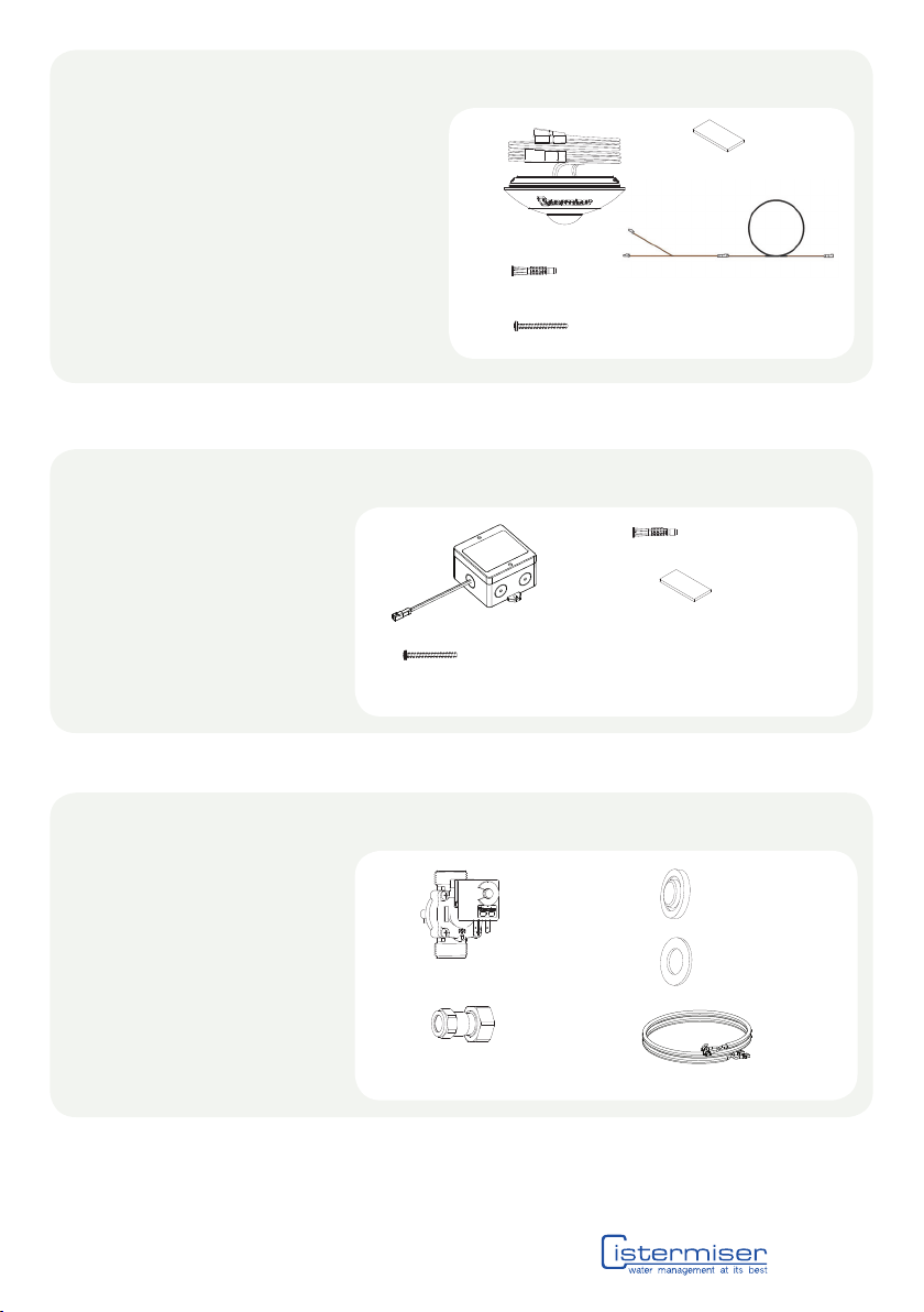
Additional Valve Kit - supplied parts
1 Solenoid valve**
2 2 x 22mm compression fittings*
3 Inlet filter*
4 Fibre washer*
5. Piggy back cable
1
2
** Solenoid valve either 15mm, 22mm, 1” or 11/4”
* Only supplied with 15mm or 22mm
4
5
Additional Sensor Kit - supplied parts
1 Sensor assembly consisting of sensor
unit and backplate
2 2 x universal fixing plug
3 2 x #6 x 1 1/2” screws
4 4 x sticky pads
5 Extension ‘Y’ Cable
1 4
2
3
sensazone Light and Fan Control (SZ/LFC) - supplied parts
1 sensazone Light & Fan Control
2 Screws x 2
3 Fixings x 2
4 Sticky Pads x 4
1
2
4
5
3
0118 969 1611 | sales@cistermiser.co.uk | www.cistermiser.co.uk
3
3

2 Guidance on system layout
Prior to installing any components, it is important to confirm the required location of the sensor(s). Once the location(s) have
been confirmed, refer to Section 3 to set up the installation.
When occupancy is
detected in the common
entrance, the water,
lights and fans will be
activated in all areas of
the washroom.
Example layout for single (common) entrance:
Scenario 1 and 2
Example layout for multiple entrances:
Scenario 3 and Scenario 4
When occupancy is
detected at one of the
entrances, the water,
lights and fans will be
activated in all areas of
the washroom.
DOOR
MINIMUM 1 METRE
MINIMUM 1 METRE
40118 969 1611 | sales@cistermiser.co.uk | www.cistermiser.co.uk

A
3 Installation schematic
Scenario 1
Scenario 2
CEILING
Max 10 metres cable length between sensor and furthest valve
Max 10 metre cable length between sensor (A) and furthest valve
Max 30 metres cable length between SZ/IF (B) and furthest valve
Cold water supply
to washroom Cold water supply
to washroom
Isolating Valve
(not supplied)
Isolating Valve
(not supplied)
Hot water supply to
washroom Hot water supply to
washroom
Grey or rainwater
supply to washroom Grey or rainwater
supply to washroom
Max 3 metres cable length from sensor to power supply
Max 100 metre cable length between SZ/IF (B) and SZ/LFC (D)
Max 1.85 metres cable length
CEILING
A
A
C
CE
E
D
B
Detection Zone: 5 metres
Detection Zone: 5 metres
2.2 metres 2.2 metres
5
0118 969 1611 | sales@cistermiser.co.uk | www.cistermiser.co.uk
Sensor(s) installation: Refer to page 7 for details
SZ/IF installation: Refer to page 7 for details
SZ/LFC installation: Refer to page 8 for details
Valve installation: Refer to page 8 for details
Mains power adapter: Refer to page 9 for details
A
B
D
C
E

Scenario 3
Scenario 4
CEILING
CEILING
A A
CEB
A
A
CE
D
B
3 Installation schematic
60118 969 1611 | sales@cistermiser.co.uk | www.cistermiser.co.uk
Max 10 metre cable length between sensor (A) and furthest valve
Max 30 metres cable length between SZ/IF (B) and furthest valve
Max 10 metre cable length between sensor (A) and furthest valve
Max 30 metres cable length between SZ/IF (B) and furthest valve
Max 100 metre cable length between SZ/IF (B) and SZ/LFC (D)
Sensor(s) installation: Refer to page 7 for details
SZ/IF installation: Refer to page 7 for details
SZ/LFC installation: Refer to page 8 for details
Valve installation: Refer to page 8 for details
Mains power adapter: Refer to page 9 for details
A
B
D
C
E
Cold water supply
to washroom
Cold water supply
to washroom
Isolating Valve
(not supplied)
Isolating Valve
(not supplied)
Hot water supply to
washroom
Hot water supply to
washroom
Grey or rainwater
supply to washroom
Grey or rainwater
supply to washroom
Detection Zone: 5 metres
Detection Zone: 5 metres
2.2 metres
2.2 metres
Max 1.85 metres cable length
Max 1.85 metres cable length
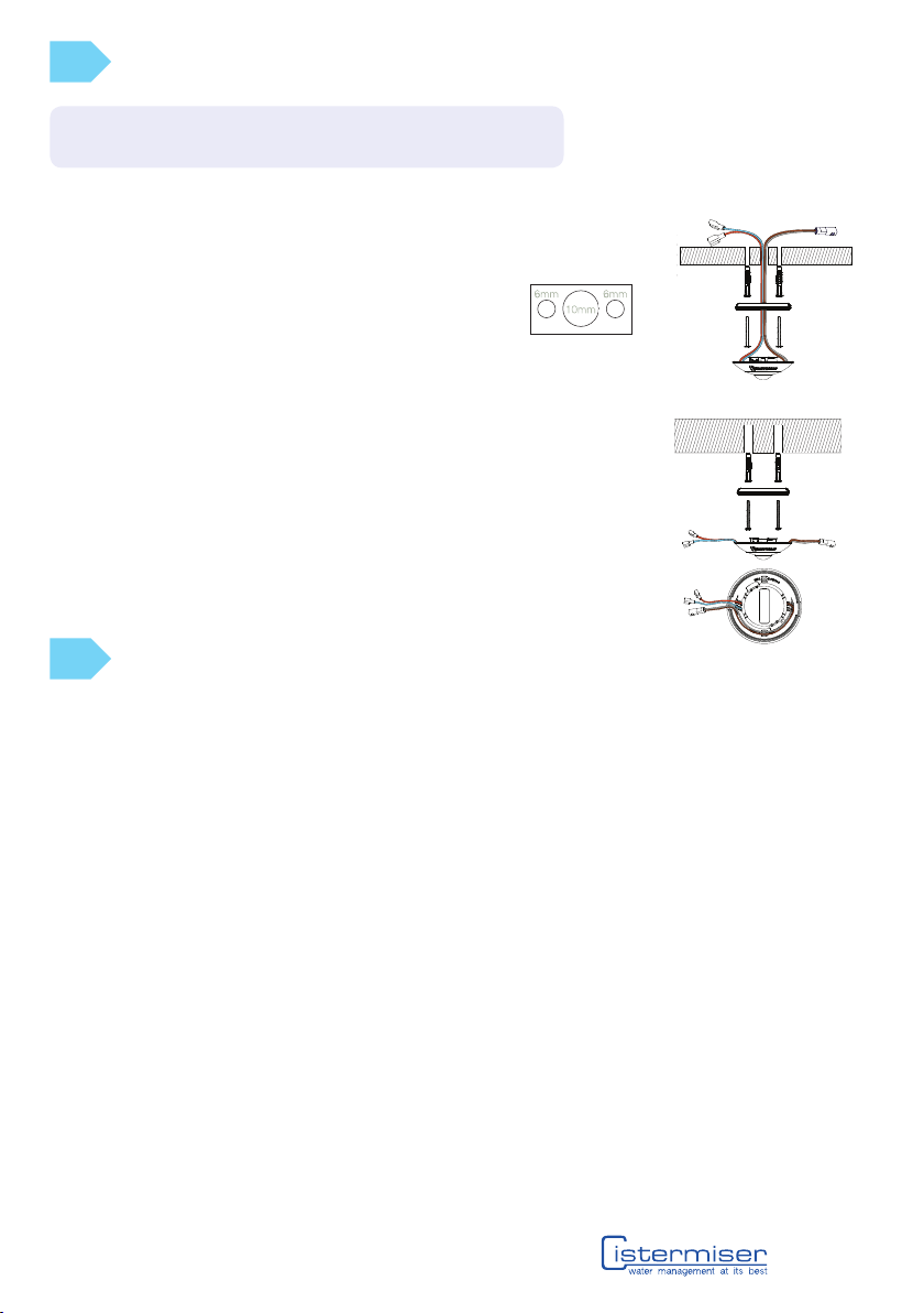
Sensor(s) installation
false ceiling
1. Detach the backplate from the sensor unit.
2. Offer the backplate to the ceiling and mark position of holes.
3. Drill 6mm diameter holes and insert Rawlplugs.
4. Drill an additional hole of 10mm diameter between the two 6mm
holes as shown here.
5. Screw the base plate to ceiling.
6. Feed the wire through the large (10mm) centre hole and secure the sensor unit to the
base plate.
7. Twist sensor unit clockwise into backplate to lock into position.
solid ceiling
1. Detach the backplate from the sensor unit.
2. Offer the backplate to the ceiling and mark the position of holes. Pay particular attention
to ensure that the ‘wire exits’ are correctly positioned for your installation.
3. Drill 6mm diameter holes and insert Rawlplugs.
4. Screw base plate to ceiling.
5. Ensure wire is fed through the ‘wire exits’ as displayed on the sensor. If the wire is
required to go out of the same exit ensure that the wire is routed around the sensor as
shown in the diagram below.
6. Secure sensor unit to base plate and twist clockwise to lock into position.
SZ/IF Installation
Position the sensazone Interface Module (SZ/IF) in accordance with the following:
1. The cable length from the SZ/IF to the furthest valve must NOT exceed 30m.
2. The cable length from the SZ/IF to the SZ/LFC must NOT exceed 100m.
3. If cables are extended 1.5mm2cable must be used.
4. Where necessary use wiring conduit to protect exposed cables.
Connecting to the SZ/IF:
Connect the sensor unit(s) to one of the SZ/IF outputs. When 2 or more sensors are required, use the extension ‘Y’ cable
provided and connect in series as shown.
Connect the SZ/LFC to the SZ/IF output or via one of the additional sensor ‘Y’ cables. Refer to D for further details on
SZ/LFC installation.
A
B
7
0118 969 1611 | sales@cistermiser.co.uk | www.cistermiser.co.uk
NB: A max of 10 sensors can be used per system. Position the sensor(s)
at least 1 metre from the entrance(s). If cables are extended 1.5mm2
cable must be used.

Single valve installations
Connect the spade connectors from any sensor unit to the solenoid
tabs taking care to connect the wires according to the label. The
solenoid cables are orange and turquoise. If these are not long enough
they can be extended by up to 10 metres.
NB: Should you require extension cables for the solenoid
valves please contact Cistermiser technical services.
Multiple valve installations
Up to 3 valves can be connected in parallel using the ‘daisy chain’ cable
provided in the additional solenoid valve kit (AVK). The AVK is available
from Cistermiser or any major plumbing merchant. Ensure that like
colours are connected. Use the ‘piggy back’ connectors to loop 2 or 3
valves together as shown opposite.
Valve installation
C
D
SZ/LFC Installation
The SZ/LFC must be connected to the SZ/IF; this can be directly to one of the 2 output cables on the SZ/IF or via an
extension”Y” cable supplied with an additional sensor kit. If required this cable can be extended up to a maximum length of
100m with 1.5mm² cable.
1. Secure the SZ/LFC to a solid surface either with screws or the sticky pads provided.
2. Remove the top cover and pierce the appropriate rubber cable gland to connect the lights and/or fans. Take care
when piercing the gland not to damage the product.
WARNING: Isolate mains supplies to lights and fans
3. Connect the live feed for the lights to the LIGHTS contactor (Ensure load does not exceed 8A)
4. Connect the live feed for the fans to the FAN contactor (Ensure load does not exceed 8A)
5. Replace lid with screws provided before restoring power.
WARNING: This is a functional switching device, and must not be used for safety or maintenance isolation!
WARNING: This device is intended for use with hazardous voltages. The installation and maintenance of this device
must be carried out by a qualified electrician in accordance with local wiring regulations. Before installing
this device, please read these installation instructions carefully.
NB: Do not install near localised heat source
NB: Where necessary use wiring conduit to protect exposed cables
80118 969 1611 | sales@cistermiser.co.uk | www.cistermiser.co.uk
NB: Valves can be connected to any sensor. Maximum 3 valves per system.
NB: For grey water/rain water harvesting. Ensure adequate filtering is fitted, a 10µm filter is recommended.
NB: For chemical water treatment. If the water system has been treated with chemical dosing, ensure the system is
thoroughly flushed before fitting any Cistermiser products. Concentrated chemicals in dead legs can damage the
product and result in failure. If the water is treated with Chlorine Dioxide (ClO2), concentration levels are maintained
below 5ppm.
NB: As with all water containing products, lime scale in hard water areas can affect the products performance. This can
result in maintenance to remove the lime scale as and when required.
Install valve on to the water supply leading into the washroom (hot, cold
and rain/grey water) or as close as practically possible to the entry point
to suit the pipe layout.

Mains power adaptor
Scenario 1
Connect the power connector from
the sensor unit to the mains adaptor.
Colour conventions are brown for
positive and grey for negative.
Wire the mains adaptor into a 1A fused spur.
Scenario 2 Scenario 3 Scenario 4
Connect the power connector for the SZ/IF to the mains adaptor. The sensor(s) and SZ/LFC are connected to
one of the SZ/IF outputs.
Power connector
E
LED indication on Sensor when connected to SZ/IF:
1 green flash per second Valve opens / Lights on / Fans on
Constant red Valves locked closed (See Section 7 - activating clean mode)
Constant amber Valves locked closed for 10 minutes (See Section 7 - activating clean mode)
Constant green Valves locked open (See Section 7 - activating clean mode)
1 red flash per second Low supply voltage (Check max cable length)
2 red flashes per second Solenoid short (Check wiring and contact Cistermiser)
9
0118 969 1611 | sales@cistermiser.co.uk | www.cistermiser.co.uk
4 Testing and commissioning
start up operation
When the sensazone is powered up the LED will be a constant amber for up to 15 seconds, after which it will flash amber
for 5 seconds. The water supply(ies) into the washroom will now be on for the default run-on time of 15 minutes. The default
run-on time can be changed to 30 minutes. See the ICU guide in section 7.
normal operation
When movement is detected, a pulse is sent to open the valve(s) and the LED will flash green once every three seconds
when a single sensor is installed. The LED will flash green once a second when installed with SZ/IF.. If movement is detected
during the run-on time the timers are re-set and will keep the valve(s) open for a further 15 or 30 minutes from the time
movement was last detected.
testing
This can be done using the Infrared Configuration Unit (ICU) which is supplied with the SZ/IF - See ICU guide in section 7 –
activating walk test.
NB: The mains power adapter
should not be further than 3
metres from the sensor.
NB: The mains power adapter should not be more than 1.85 metres from the SZ/IF.

SZ/IF
Rated: SELV
Maximum number of sensors: 10
Maximum number of valves: 3
Max cable length from SZ/IF to last valve: 30m (1.5mm2cable)
Max cable length from SZ/IF to SZ/LFC: 100m (1.5mm2cable)
Power requirements: 6v DC regulated mains adaptor (supplied with sensazone)
Ingress Protection: IP54
SZ/LFC
Rated voltage: 240VAC
Rated current: 8A
Making capacity: 16A for 1 second
Breaking capacity: 4000VA
Max wire size: 2.5mmsq
Ingress Protection: IP54
Circuits must have overload/fault protection of 10A or less.
Circuit protection and wire size must meet local wiring regulations.
NB: Rated Current is for a resistive load - when using inductive/capacitive loads such as fluorescent ballasts, please
derate the load to ensure the inrush current does not exceed the contact making capacity.
Warning: This is a functional switching device, and must not be used for safety or maintenance isolation.
Warning: This device is intended for use with hazardous voltages. The installation and maintenance of this device must
be carried out by a qualified electrician in accordance with local wiring regulations. Before installing this device, please
read these installation instructions carefully.
SZ/ASK
Control classification: Independent
Maximum load: 3 x 2W 0.33A (6VDC) EMC emissions tested at load
Rated temperature range: 0-40 deg C
Action classification: Type 1.Y
Pollution classification: Degree 1
Ingress protection: IP55 or IP65 (with respect to room when smooth,
non-porous ceiling tile used)
factory settings
Range: ~2.2m high x 5m diameter
Sensitivity setting: Medium
Hygiene rinse: On (30 min every 12 hours)
Run-on time: 15 minutes
Additional fan run-on time: Off (Default)
15mm & 22mm valves: Max pressure 6 bar Min pressure (dynamic) 0.5 bar
1” and 1.25” valves: Max pressure 5 bar Min pressure (dynamic) 0.5 bar
Ambient Temperature Range: Operating 0 to +40°C Storage -25 to +40°C
LED indication on SZ/LFC (isolate mains supply to lights and fans before removing cover to
reveal status LED)
Constant Green System idle and OK
1 green flash per second Fan on
2 green flash per second Fans and lights on
1 red flash per second Low supply voltage (Check wiring and contact Cistermiser)
2 red flashes per second Comms failure (Check wiring and contact Cistermiser)
LED indication on SZ/IF:
Constant green System idle and OK
1 green flash per second Valves open/lights on/fans on
Red flash Fault (Check wiring and contact Cistermiser)
Usage advice and specification
Dieses Handbuch passt für folgende Modelle
2
Inhaltsverzeichnis


