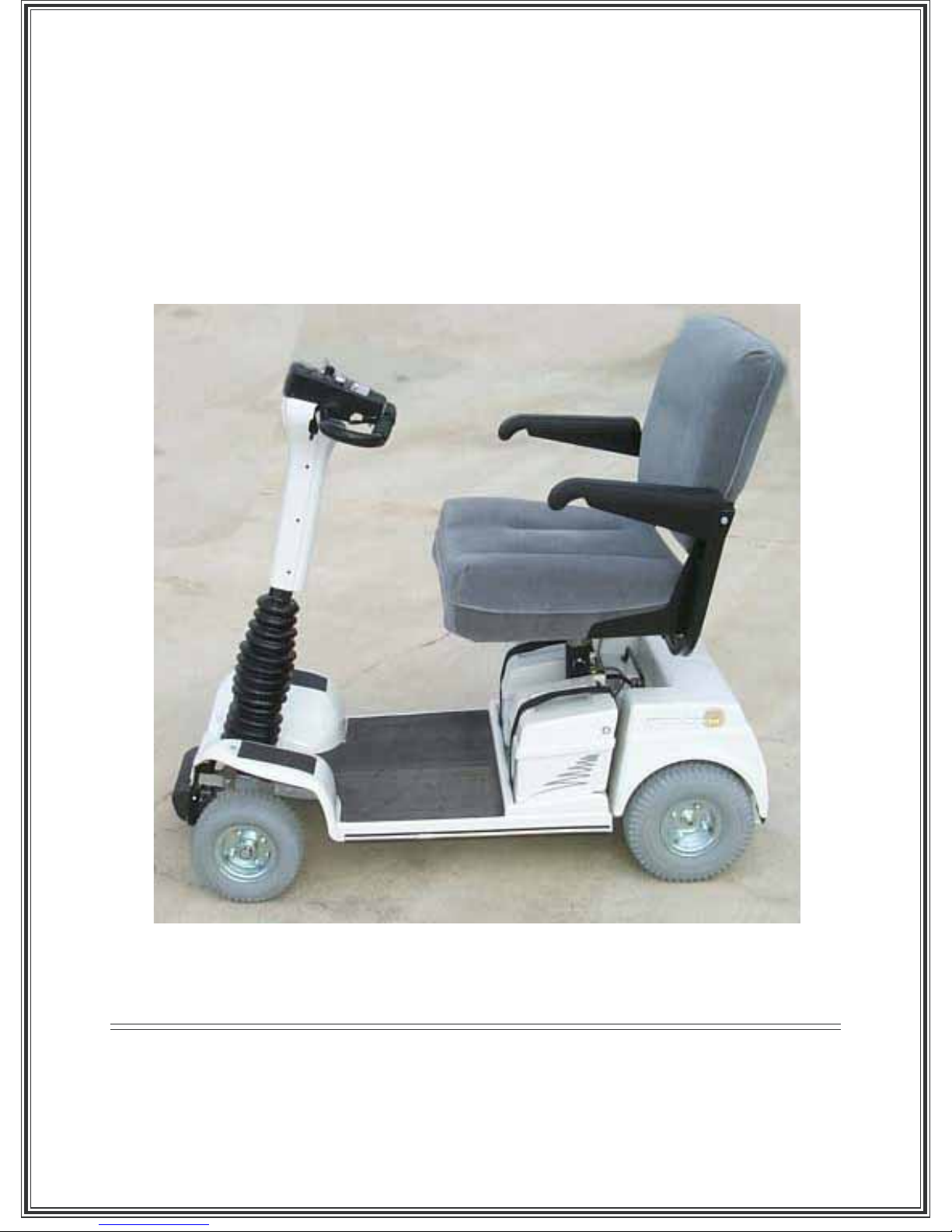
ConvaQuip Solo XT550 Bedienungsanleitung

Solo XT550
OWNERS GUIDE
IMPORTANT:Read before using!
C24AB
ConvaQuip Ind., Inc.
P.O. Box 3417
Abilene, TX 79604
Toll 800-637-8436
Fax 325-677-7217

IC24AB
CONTENTS
SECTION 1 - Introduction ..................................................................... 1
SECTION 2 - Safety......................................................................... 2 - 3
SECTION 3 - A First Look At Your Solo XT550 .................................... 4
SECTION 4 - Assembly Instructions..................................................5-6
SECTION 5 - Seat Adjustment .............................................................. 6
SECTION 6 - Disassembly of Your Solo XT550 For Transport ......7 - 8
SECTION 7 - Operating Controls for Delta Tiller............................9 - 10
SECTION 8 - Operating Sequence ..................................................... 11
SECTION 9 - Brake Systems ............................................................. 12
SECTION 10 - Batteries ........................................................................ 13
SECTION 11 - Battery Charging ................................................... 14 - 15
SECTION 12 - Routine Maintenance .................................................... 16
SECTION 13 - T roubleshooting ............................................................ 17
SECTION 14 - Specifications ............................................................... 18
SECTION 15 - Electromagnetic Interference ............................... 19 - 20
SECTION 16 - California Proposition 65 Warnings .............................. 21
SECTION 17 - Warranty ....................................................................... 22

C24AB1
INTRODUCTION
SECTION 1
Thank you for choosing the Solo XT550 as your new personal
mobility vehicle. Your Solo XT550 has been designed and
manufactured in America with a great deal of pride, and has been
thoroughly tested prior to shipment. We sincerely hope that your
ownership of a Solo XT550 will bring you many years of freedom and
enjoyment. To that end we ask that you read and understand this
Owners Manual prior to operation, and that you pay particular attention
to the safety precautions listed in Section 2, and in various places
throughout this manual.
Although maintenance on your Solo XT550 is minimal, it is important
that you follow the maintenance instructions listed in Section 12 of this
manual.
Please record the Serial Number of your Solo XT550 on this page.
This is necessary in the event you need to order repair parts. The
serial number is located on a tag under the lifting handle on the rear
drive unit. Also be sure to keep your invoice in a safe place. This is
necessary in the event you require service under the warranty.
SERIAL NUMBER xxxxxxxxxxx_______________
ENJOY YOUR Solo XT550 AND ABOVE ALL - RIDE SAFELY

C24AB2
SAFETY
SECTION 2
It is the responsibility of the OWNER to read this manual and to know the proper
operating precautions and requirements and to make them known to all who may
work with the equipment or be in the working area. Unsafe practices may result in
serious injury or death and equipment damage!
Failure to read this manual is a misuse of the equipment!
SAFETY ALERT SYMBOL
Watch for this symbol. It means:
ATTENTION!
BECOME ALERT!
YOUR SAFETY IS INVOLVED!
The SAFETY ALERT SYMBOL is used to identify potential hazards
and to call your attention to instructions concerning your personal
safety. Read the instructions that accompany this symbol and be
aware that to disobey or disregard the message may result in
personal injury or death.
PLEASE NOTE:
The words DANGER, WARNING, and CAUTION are used throughout this manual to
designate the level of a hazards seriousness.
DANGER: Indicates an imminently hazardous situation which, if not avoided, will result in
death or serious injury. This word is limited to the most extreme situations.
WARNING: Indicates potentially hazardous situation which, if not avoided, could result in
death or serious injury.
CAUTION: Indicates potentially hazardous situation which, if not avoided, may result in
minor or moderate injury. It may also be used to alert against unsafe practices.

C24AB3
GENERAL SAFETY PRECAUTIONS
IMPORTANT: Please be sure you read and understand these Safety Precautions, and
observe them at all times.
√BE SURE to read this Owners Manual before operation.
√ALWAYS reduce speed and use extreme caution when operating indoors or in crowded areas.
√DO NOT carry passengers.
√DO NOT turn the key on until you are properly seated with your feet on the floor.
√DO NOT operate unless the seat is locked facing forward, and the tiller is locked in position.
√DO NOT operate on steep downhill slopes. When going downhill, reduce speed. ALWAYS operate
straight up or down on a hill. NEVER drive “across the slope” on an incline.
√DO NOT get off the Solo XT550 until you have turned the key switch off. Remove key when the Solo
XT550 is unattended.
√DO NOT operate on inclines greater then 6°
√DO NOT make sharp turns while traveling at high speeds or when operating on inclines or uneven
surfaces.
√ALWAYS reduce speed before turning.
√DO NOT adjust tiller angle while moving.
√DO NOT use the Solo XT550 as a seat in a motor vehicle. It DOES NOT meet Federal safety stan-
dards for vehicle seating.
√DO NOT operate your Solo XT550 on streets or roads.
√DO NOT operate the Solo XT550 if the Parking Brake is not operating properly. Refer to Section 8
and to the Maintenance Instructions for details.
√DO NOT operate when carrying a weight greater than 550 lbs.
√ALWAYS disconnect the batteries when transporting the Solo XT550.
√DO NOT disassemble the tire/rim assembly while the tire is pressurized.
√ALWAYS use extreme caution when operating on sidewalks or uneven surfaces.
√ALWAYS use extreme caution when operating near or around electromagnetic equipment, i.e. cellular
phones, or ham radios. Refer to section 16 for more details.
√DO NOT allow your scooter to get wet. Always use a cover if your scooter is left outdoors, or trans-
ported in an open pickup box, in a trailer, or on a lift which is mounted on the outside of a vehicle.
√ALWAYS use the lowest comfortable seat position when operating your Solo XT550 to increase its
stability.
DO NOT operate the Solo XT550 until you are confident of your ability to do so safety. If you need further
instruction, contact yourAuthorized Dealer.

C24AB4
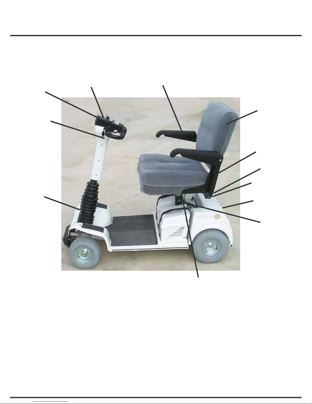
A FIRST LOOK AT YOUR SOLO XT550
SECTION 3
This section describes the major parts and features of your Solo XT550. Many of the
features are described in more detail in other parts of this manual. Refer to the appropriate
Sections as listed.
1. Accelerator Control Panel: (Section 7).
2. Tilt Release Lever: Tiller angle is adjustable from handlebar without reaching down.
3. Seat Height Adjustment, Front/Back Seat Adjustment: (Section 5).
4. Battery Charger Plug: (Section 11).
5. Headlight. (optional)
6. Rear Drive Unit: Transaxle drive for quieter operation and a rugged 24 volt DC motor.
7. Brake Release Lever: Allows the cart to be pushed (Section 9).
8. Seat Swivel Release: Positive lock, not friction lock.
9. Removable Armrests: Width of Armrests is adjustable for your comfort.
10.Fold-up Armrests: Makes getting on and off Solo XT550 easier.
11. Folding Seat.
12.Taillights (optional)
FIGURE 1
1
2
3
4
56
7
8
9
10
11
12

C24AB5
ASSEMBLY INSTRUCTIONS
SECTION 4
If your Solo XT550 has been assembled prior to delivery to you, please disregard this
section. Otherwise, proceed as follows:
1. Open Box No. 1 Containing the Front Frame Section. Open the box packed on the floor
and remove the Seat Post assembly.
2. Open Box No. 2 containing the Rear Drive Unit and the Seat.
3. The seat is adjustable in three positions (front to back). Determine which position you
want and adjust at this time according to instruction in Section 5.
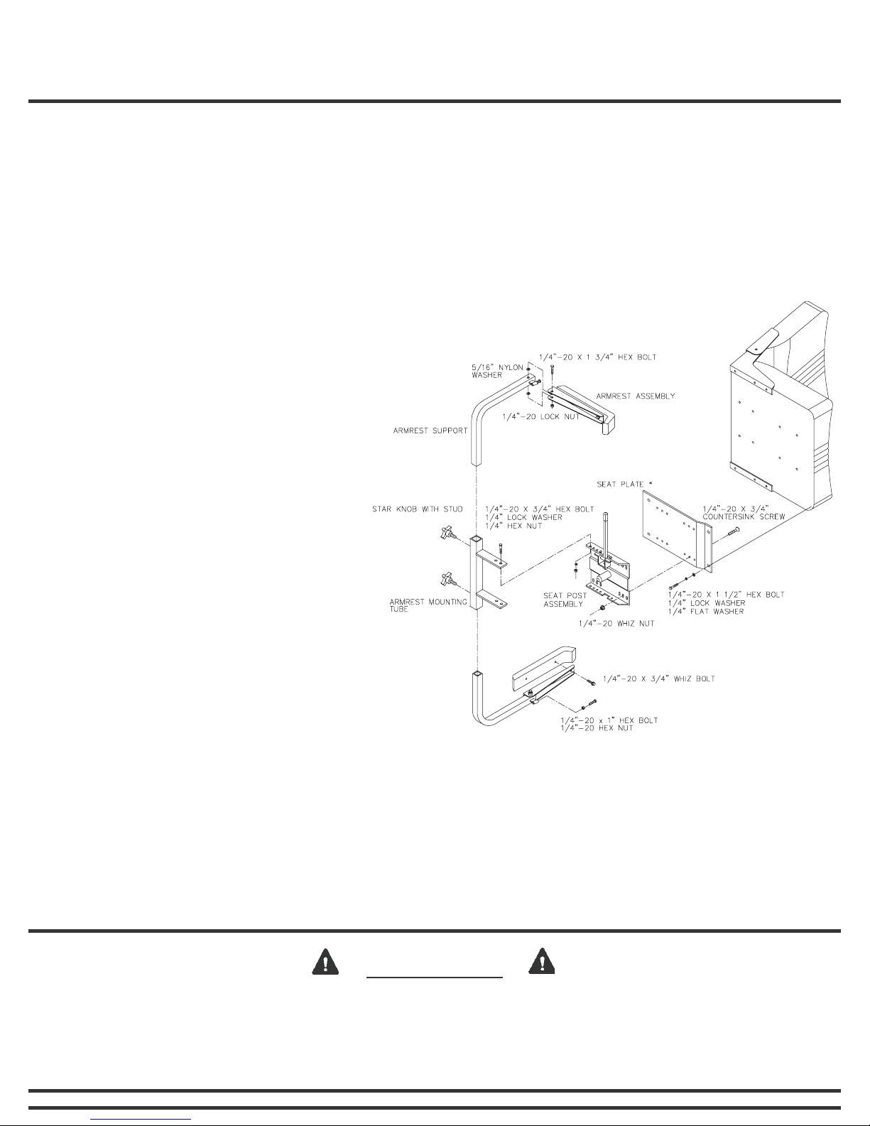
4. Bolt the Seat Post assembly
and Armrest Mount Tube to the
seat bottom with six ¼” bolts,
lockwasher, and flatwashers
packed in the parts bag (fig 2 &
3). On XT550 seats you must
use a “seat plate” between the
seat post and the seat (fig 3).
5. Attach the padded Armrests to
the curved Armrest Support with
¼” x 1¾” bolts and lock nuts.
Two 5/16” nylon washers go
between the Armrest and
support (fig 2 & 3).
6. Connect Front Frame Section
and Rear Drive unit according to
the instructions in Section 6.
7. Install the Seat by placing the
Seat Post in the Seat Base on
the Solo XT550. The seat
height is adjustable by
positioning the seat height adjustment tube in one of the holes provided.
ALWAYS USE THE LOWEST POSITION THAT IS
COMFORTABLE FOR YOU. See Section 5.
8. Slide the Seat Arms into the Armrest Support and lock them in place with the two black
plastic knobs from the parts bag. The Seat Arms are adjustable by loosening the
knobs, sliding the Arms in or out, and retightening the knobs.
CAUTION
We recommend that you do not adjust the arms out so far that they are wider than
the base of the cart, they may catch on doorways or other objects, causing damage
to your Solo XT550 or injury to yourself or others. If it is necessary to do so (such as
on the extra large seat) use extra care.
FIGURE 2

C24AB6
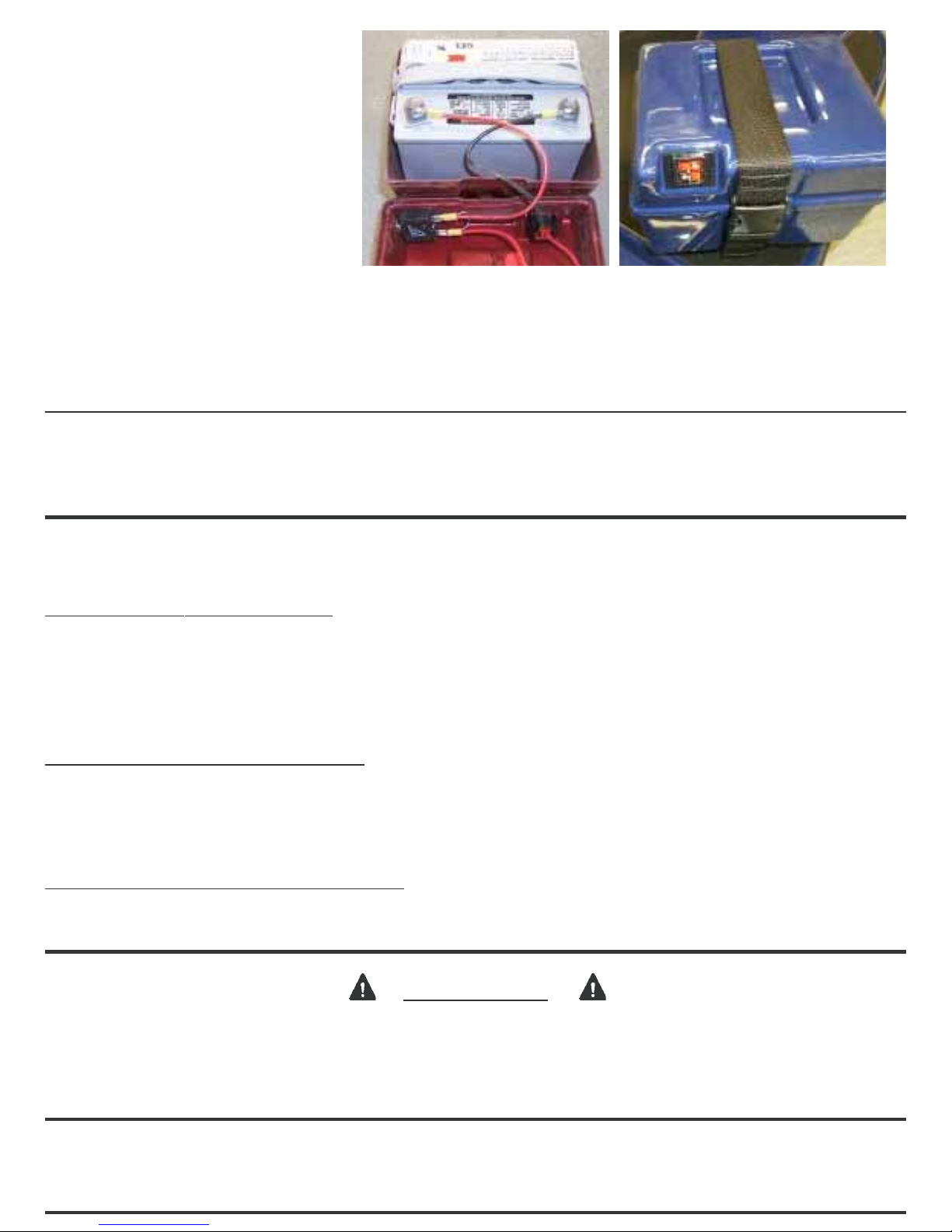
9. Connect the black lead to
the negative (-) post of the
battery, and the red lead to
the positive (+) post of the
battery with the bolts and
nuts supplied with the
batteries. (figure 3).
10.Place the battery in the
battery box and place the
cover on the battery box.
Place the lifting strap
around the battery box and
fasten it in place snugly. (figure 4). FIGURE 4FIGURE 3
SEAT ADJUSTMENT
SECTION 5
The seat on your Solo XT550 is adjustable up and down. In addition, the width of the
armrests are adjustable, and they may be removed from the seat if necessary.
SEATHEIGHT ADJUSTMENT - There are four height positions. ALWAYS USE THE
LOWEST SEAT POSITION THAT IS COMFORTABLE FOR YOU. To change positions,
remove seat, pull the locking pin from the lower seat base, put the height adjustment tube
in the desired location, and lock in place with pin.
FRONT TO BACK ADJUSTMENT - There are three positions. To change position, remove
the seat plate assembly from the bottom of the seat. Remove the four bolts holding the
upper seat post to the seat plate. Bolt the upper seat post back to the seat plate in the set
of holes that provides the proper seat location (Fig 2).
ARMREST ADJUSTMENT/REMOVAL - Loosen the black plastic knobs on the bottom of
the seat and slide the arms in and out. Tighten knobs when adjusted.
CAUTION
Use caution when adjusting the armrest widths. If the arms are wider than the frame
of the Solo XT550, they may catch on the side of the doorway or other obstacle,
causing damage to the Solo XT550 and possible injury to yourself.

C24AB7
DISASSEMBLY OF YOUR SOLO XT550 FOR TRANSPORT
SECTION 6
One of the most important features of your Solo
XT550 is the ease with which it disassembles for
transport in a car or van.
STEP 1 - Fold the back down on the seat and
remove the seat by lifting straight up.
NOTE: Theswivelmustbeinalocked
position (not free swiveling) in
order to remove the seat.
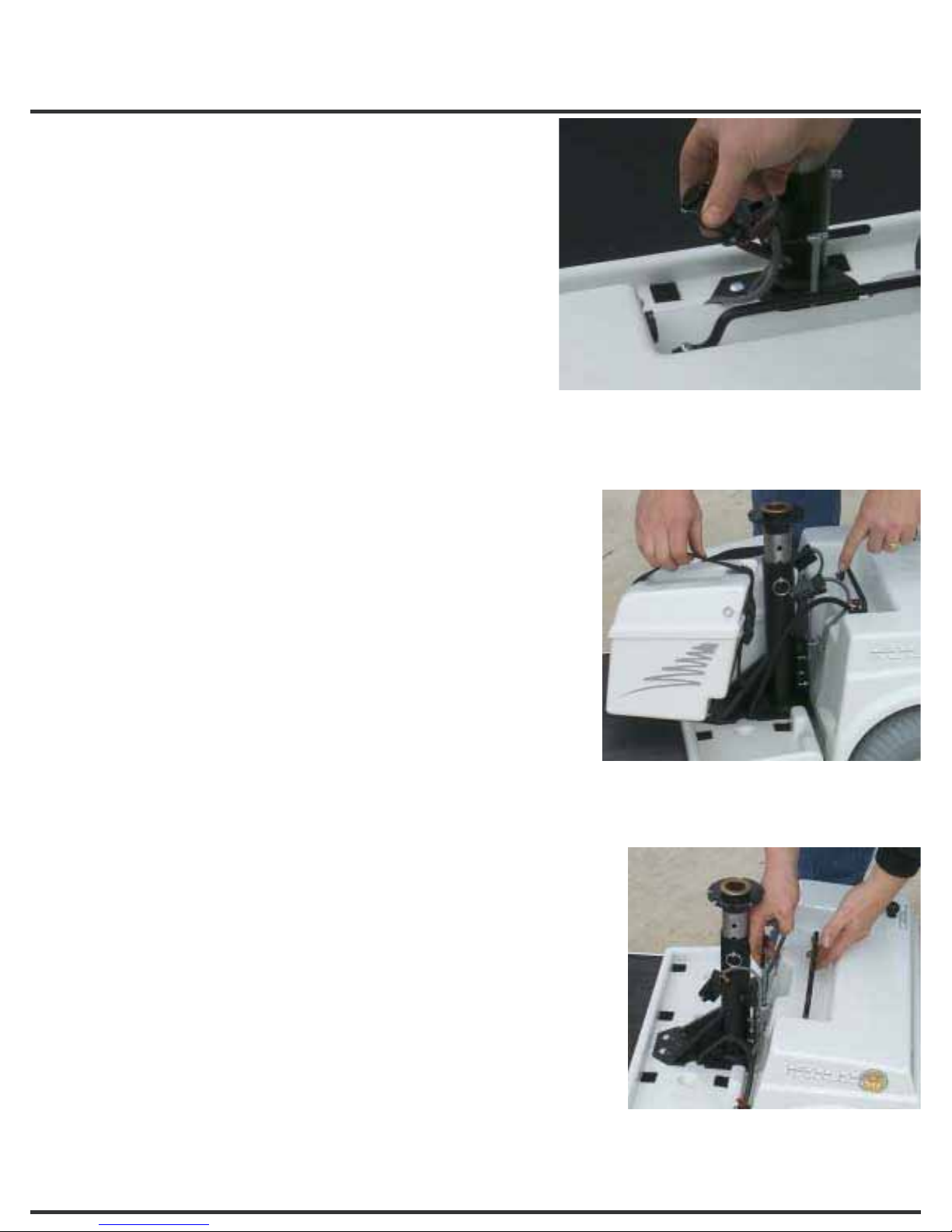
STEP 2 - Disconnect both battery cables.
Disconnect the motor cable from the
Rear Drive Unit. See Figure 5.
STEP 3 - Grasp the Battery Strap and lift each Battery
out. See Figure 6.
STEP 4 - Grasp the handlebar with one hand. With the
other hand, grasp the “T” handle directly behind
the seat base. See Figure 7.
STEP 5 - Lift up on the handle. Continue to lift until the
Front Frame Section is clear of the Rear Drive
Unit. Lifting the “T” handle both releases the
latch and allows you to lift the front away from
the Rear Drive Unit. See Figure 7.
STEP 6 - Fold the tiller down until it latches. The Front
Frame Section may be picked up with one hand
on the “T” handle and the other hand under the
front bumper. Figure 7
Figure 5
Figure 6

C24AB8
TO RE-ASSEMBLE THE SOLO LTD:
STEP 1 - Place the Rear Drive Unit on the
ground, making sure it is tilting back
and resting on the rear “anti-tip”
wheels. Place the drive lever into
the drive position to lock the brake
and prevent the unit from rolling
while attaching the front of the cart.
STEP 2 - Stand the tiller straight up and grasp
the handlebar with one hand. Grasp
the “T” handle with the other hand.
Lift up on the “T” handle and set the
Front Frame in the “V” groove on the
Rear Drive Unit. Release the “T”
handle and allow the front frame to
drop down engaging the latch. Check to be sure
the latch is engaged.
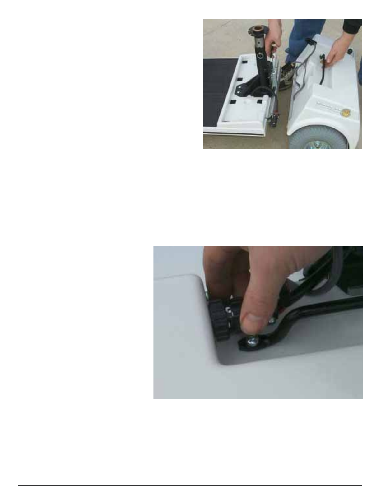
STEP 3 - Raise the tiller up, reconnect the battery and motor cables, and reinstall the
seat.
NOTE: When reconnecting the motor cable, align the two yellow dots. See
Figure 9.
Figure 8
Figure 9
Inhaltsverzeichnis
Andere ConvaQuip Mobilitätshilfe Handbücher
Beliebte Mobilitätshilfe Handbücher anderer Marken

Rhythm Healthcare
Rhythm Healthcare B3800F Bedienungsanleitung

AMF-BRUNS
AMF-BRUNS PROTEKTOR Bedienungsanleitung

Drive DeVilbiss Healthcare
Drive DeVilbiss Healthcare OTTER Bedienungsanleitung

Rhythm Healthcare
Rhythm Healthcare C500U Bedienungsanleitung

Lumex
Lumex RJ4200A Bedienungsanleitung

Rebotec
Rebotec Jumbo Bedienungsanleitung