Cormach TOUCH MEC 1000 SONAR Montageanleitung

WHEEL BALANCERS
TOUCH MEC 1000
SONAR
TECHNICAL
SUPPORT MANUAL
UK


Technical Support Manual – 03/2017 Rel. 0 Page 1
CONTENTS
1. ACCESS TO THE SERVICE “MENUS”.................................................................................................................................................2
2. ACCESSING THE TEST PROGRAMS ..................................................................................................................................................6
2.1 Shaft rotation speed test.....................................................................................................................................................7
2.2 Pick-up signals test ..............................................................................................................................................................9
2.3 Voltage – frequency converter test...................................................................................................................................12
PICK-UP SPRING PRE-LOAD ADJUSTMENT ...................................................................................................................................14
2.4 ENCODER disc test.............................................................................................................................................................15
3. ACCESSING THE CONFIGURATION “MENUS”................................................................................................................................17
3.1 Enable/Disable distance/diameter sensor ........................................................................................................................19
3.2 Enable/Disable width sensor.............................................................................................................................................21
3.3 Sensors calibration ............................................................................................................................................................23
3.3.1 Distance sensor operation test.......................................................................................................................................24
3.3.2 Diameter sensor calibration ...........................................................................................................................................26
3.3.3 SONAR DEVICE operation test........................................................................................................................................28
3.4 Enable or disable electromagnetic stopping brake ...........................................................................................................30
3.5 Enable or disable the lighting led ......................................................................................................................................31
3.6 Enable or disable the LASER ..............................................................................................................................................33
3.7 MICRO WHEEL GUARD operation test ..............................................................................................................................34
4. MACHINE CALIBRATION................................................................................................................................................................36
4.1 When to carry out machine calibration .................................................................................................................................36
4.2 Machine calibration for the CAR/SUV Wheel Types ..............................................................................................................36
4.3 Machine calibration for the MOTO wheel type .....................................................................................................................42
5. ERROR AND WARNING CODES......................................................................................................................................................46
6. ACOUSTIC SIGNALS .......................................................................................................................................................................48
7. SPECIAL VISUAL SIGNALS ..............................................................................................................................................................48
8. TROUBLESHOOTING......................................................................................................................................................................48
9. ELECTRICAL DIAGRAM ..................................................................................................................................................................50
Cormach s.r.l. reserves the right to make any change to products in order to improve them.
Cormach s.r.l. reserves the right to make any change to this manual without notice.

Technical Support Manual – 03/2017 Rel. 0 Page 2
1. ACCESS TO THE SERVICE “MENUS”
Inside the SERVICE menu, the machine has a series of CONFIGURATION programs to manage the machine settings and TESTS to help
detect any anomalies.
To access the SERVICE mode, proceed as described below:
Ph.
1
Switch the machine ON by
pressing the main switch on the
back of the wheel balancer, then
wait for the test to
verify the
software version.
2
In case of defects please report
the software version that appears
in the box inside the top left box.
3
Press on icon.
Technical Support Manual – 03/2017 Rel. 0 Page 3
4
At the end of the test, the
machine is in NORMAL mode.
5

Technical Support Manual – 03/2017 Rel. 0 Page 4
6 Press on icon to exit the SERVICE
mode and enter in NORMAL
mode.
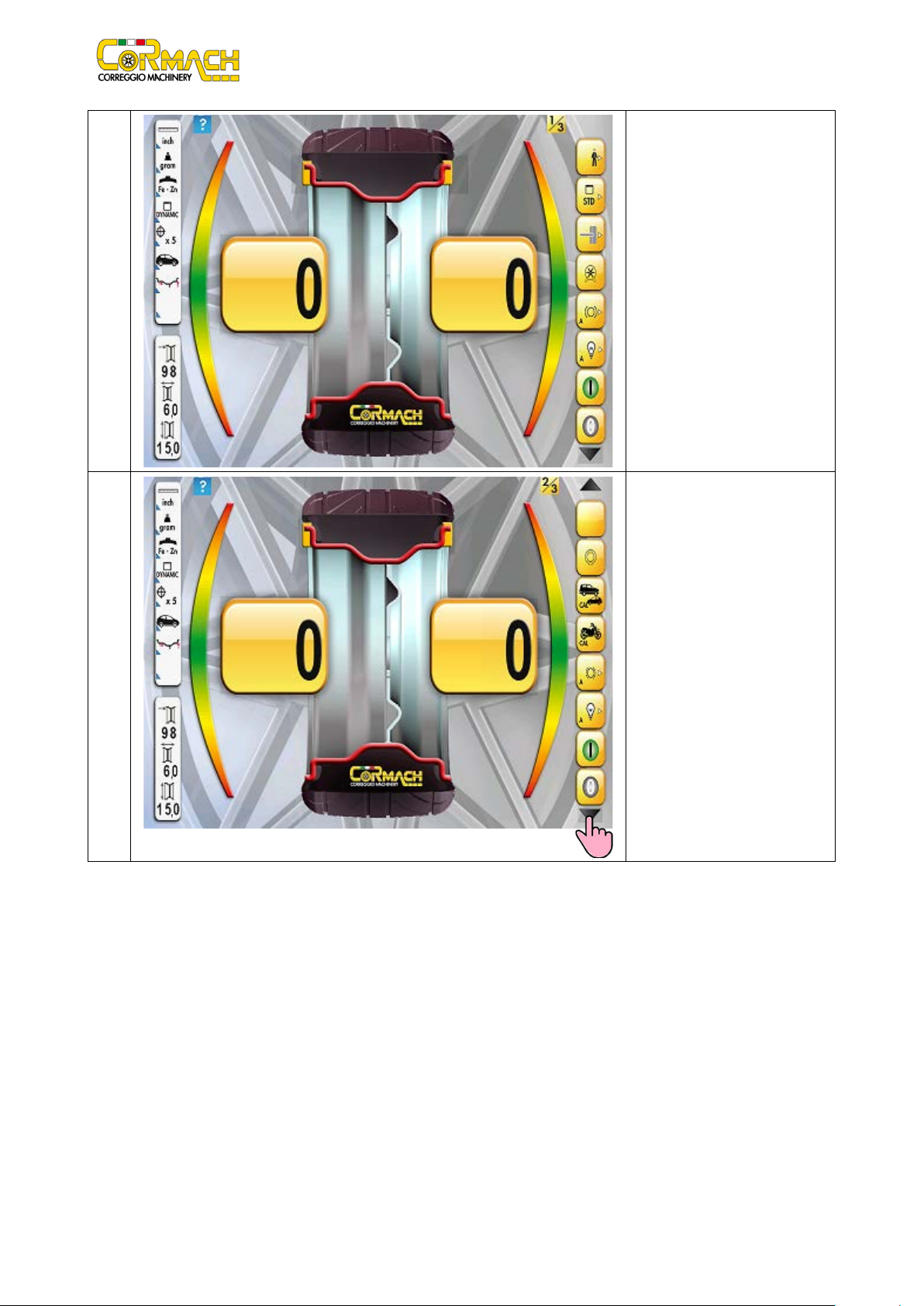
Picture F1.1: SERVICE menu
The programs can be selected in SERVICE mode BY PRESSING ON THE MONITOR THE ICONS .

Technical Support Manual – 03/2017 Rel. 0 Page 5
Table 1.1: CONTROL ICONS key
Icon
Meaning
Launch number counter selection icon.
Test program menu selection icon.
Configurations menu activation icon.
Electromagnetic brake activation icon.
Illuminator activation icon.
TOUCH SCREEN monitor test and calibration icon.

Technical Support Manual – 03/2017 Rel. 0 Page 6
2.ACCESSING THE TEST PROGRAMS
The TEST PROGRAMS are listed in table T2.1.
Table T2.1: "TEST PROGRAMS" Menu Options
Icon
Meaning
Shaft rotation speed test selection icon.
Pick-up signal test selection icon (This also controls the parameters that affect the signal).
Shaft imbalance test enabling icon.
Bearing smoothness test enabling icon (Reserved for Cormach Technical Assistance Service).
Encoder disc reading test selection icon.
Voltage - frequency converter test selection icon.
Brake calibration program selection icon (Reserved for Cormach Technical Assistance Service).
Electromagnetic brake torque test program selection icon (Reserved for Cormach Technical
Assistance Service).

Technical Support Manual – 03/2017 Rel. 0 Page 7
2.1
Shaft rotation speed test
This menu option is used to run the shaft rotation speed test. This test allows you to control the number of shaft RPMs during the
launch. A number indicating the speed of the shaft will be viewed on the right display.
To access the RPM TEST program, proceed as described below:
Ph.
1 Press on icon.
2 Press on icon.

Technical Support Manual – 03/2017 Rel. 0 Page 8
3
Lower the wheel guard: the
machine will run a launch.
4
NOTE: the speed of rotation also depends on the frequency of the main supply. The
nominal speed of rotation stated in table T11.2 refers to a frequency of 50 Hz. If the
frequency, in that country, is 60 Hz, the speed of rotation will be 20% greater (if motor
and pulley are the same).
If the speed of rotation is much lower than stated, ensure that the main supply voltage
does not drop excessively during rotation. If the main supply voltage is correct, check
the belt tension. If the belt tension is correct, check the motor and the PWRB board.
At the end of the launch, the
screen will display the speed of
rotation in RPM (revolutions per
minute). It is possible to repeat
rotation every time it is necessary.
The nominal speed of rotation
must be between 135 ÷ 145
RPM as stated in table T8.2.
Inhaltsverzeichnis
Andere Cormach Radwuchtmaschine Handbücher

Cormach
Cormach MEC 200 TRUCK Bedienungsanleitung

Cormach
Cormach GEO 15 Bedienungsanleitung

Cormach
Cormach MEC 1 Montageanleitung

Cormach
Cormach GEO 15 Bedienungsanleitung

Cormach
Cormach GEO 10 Bedienungsanleitung

Cormach
Cormach TOUCH MEC 100 Bedienungsanleitung

Cormach
Cormach MOTO MEC Bedienungsanleitung

Cormach
Cormach MEC 810VD-VDL-VDBL Bedienungsanleitung

Cormach
Cormach MEC 5 Montageanleitung


