
Cozy Breeze FS40-U3X Bedienungsanleitung

OWNER’S MANUAL
READ AND SAVE THESE INSTRUCTIONS
16" OSCILLATING STAND FAN
MODEL: FS40-U3X
1

CAUTION
Read the Rules for Safe Operation and Instructions Carefully.
WARNING
When using electrical appliances, basic safety precautions should always be followed
to reduce the risk of fire,electric shock, and injury to persons, including the following:
1. Read all instructions before using this appliance.
2. Use fan only for purposes described in the instruction manual
3. To protect against electrical shock,do not immerse unit, plug or cord in water or
spray with liquids, plug the appliance directly into a 120V AC electrical outlet.
4. Close supervision is necessary when any appliance is used by or near children.
5. Unplug from outlet when not in use, when moving fan from one location to another,
before putting on or taking off parts and before cleaning.
6. Avoid contact with moving parts.
7. Do not operate in the presence of explosive and /or flammable fumes.
8. To avoid fire hazard, NEVER place the cord under rugs or any parts near an open
flame,cooking or other heating appliance.
9. Do not operate any appliance with a damaged cord or plug after the appliance
malfunctions, or has been dropped/damaged in any manner.
10. The use of attachments not recommended or sold by the appliance manufacturer
may cause hazards.
11. Do not let the cord hang over the edge of a table counter or come in contact with
hot surfaces or leave exposed to high traffic areas.
12. Do not use outdoors.
13. To disconnect, grip plug and pull from wall outlet. Never yank on cord.
14. Always use on a dry, level surface.
15. Do not operate fan until fully assembled with all parts properly in place.
16. This product is intended for household use ONLY and not for commercial or
industrial applications.
17. WARNING: To reduce the risk of electrical shock and injury to persons, do not use
in window.
18. WARNING: To reduce the risk of fire or electric shock, DO NOT use this fan with
any solid-state speed control device.
19. This product uses overload protection (fuse). A blown fuse indicates an overload or
short-circuit situation. If the fuse burns out, unplug the product from the outlet.
Replace the fuse as per the user servicing instructions (follow product marking for
proper fuse rating) and check the products.If the replacement fuse blows, a
shortcircuit may be present and the product should be discarded or returned to an
authorized service facility for examination and/or repair.
20. Do not run cord under carpeting. Do not cover cord with throw rugs, runners,or
similar coverings. Do not route cord under furniture or appliances. Arrange cord away
from traffic area and where it will not be tripped over.
2
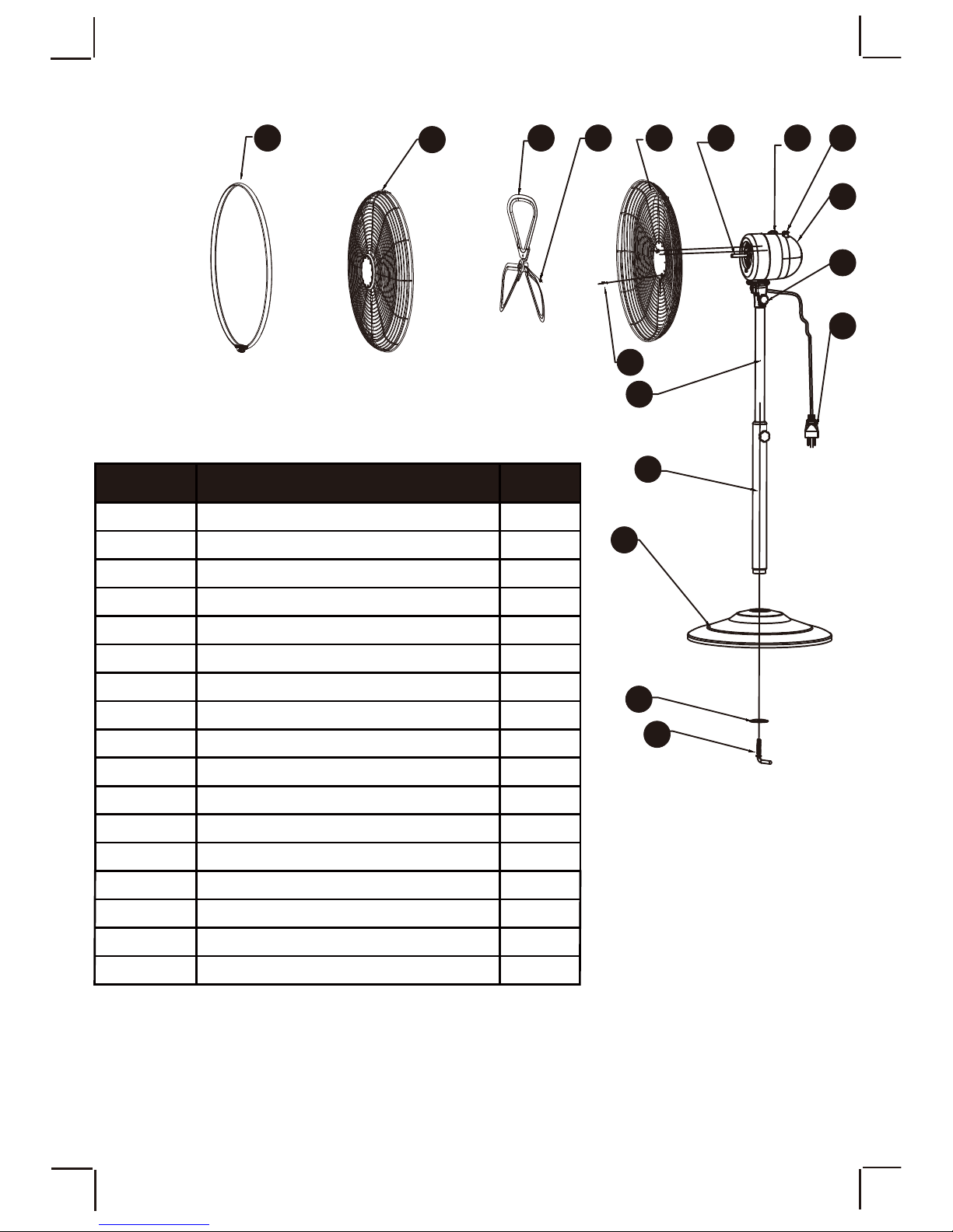
PART DIAGRAM
ABCDE
F
G
H
I
J
K
L
MN
O
P
Q
3
Grille Ring
Front Grille
Fan Blade
Blade Screw
Back Grille
Screw
Moror Shaft
Inner Pole
Telescope Pole
Base
Washer
7 Finger Screw
A
B
C
D
E
F
G
H
I
J
K
L
1
1
1
1
1
1
1
1
1
1
1
1
PART DESCRIPTION UNIT
Switch
Oscillation Knob
Motor Housing
Tilt Adjustment Knob
Plug
M
N
O
P
Q
1
1
1
1
1
TOOLS REQUIRED: Phillips screwdriver
ASSEMBLY
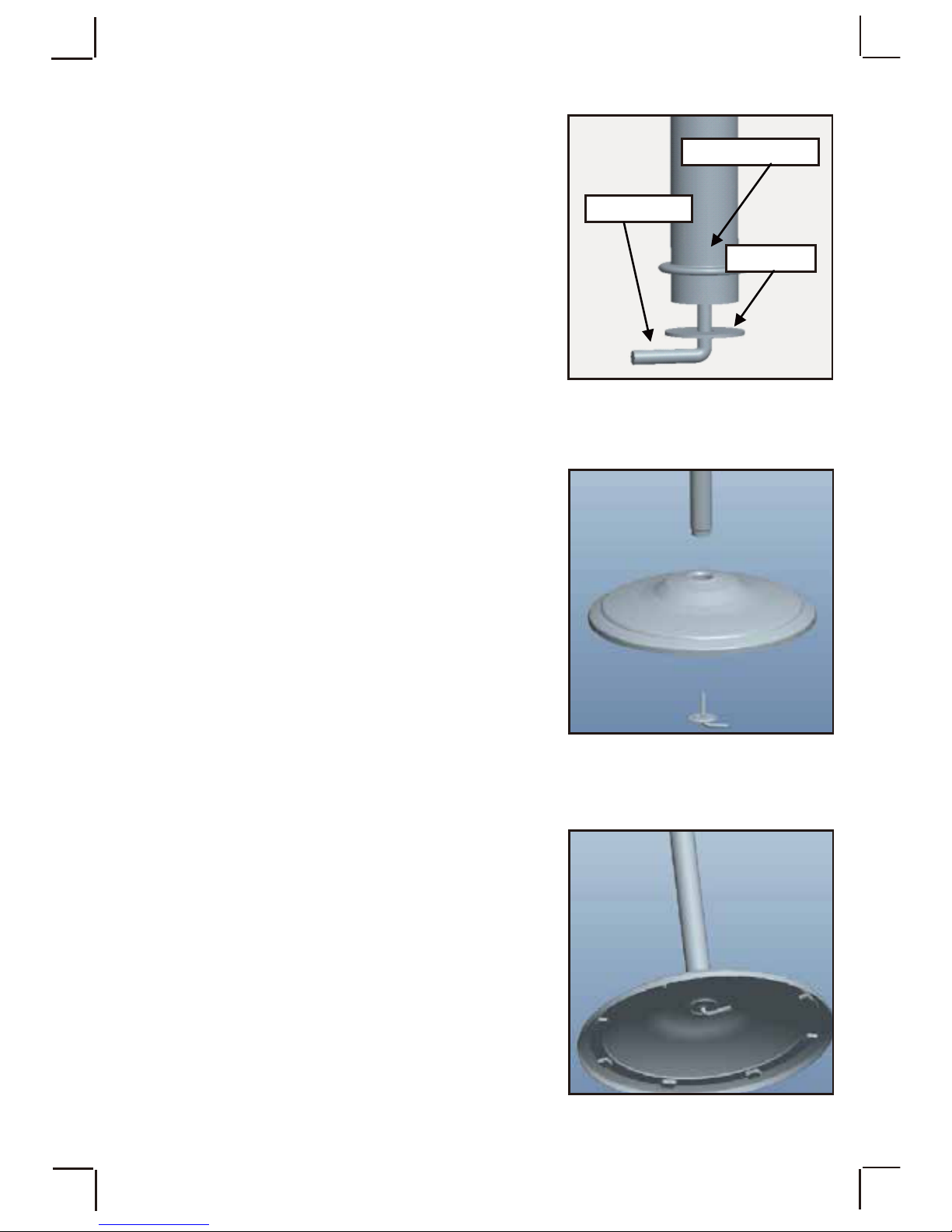
BASE ASSEMBLY
1. Loosen the 7 Finger Screw and Washer
counter-clockwise from the bottom of
Telescope Pole. Figure 1.
2. Insert the Telescope Pole to the Base,
and put the Washer and 7 Finger Screw
together. Figure 2.
3. Tilt the Base and tighten the 7 Finger
Screw into the Telescope Pole
clockwise. Figure 3
Figure 2.
Figure 3.
4
Figure 1.
finger screw
Washer
Telescope pole

4. Unscrew the Height Adjustment Knob
counter-clockwise, Figure 4.
5. Raise the Inner Pole to desired height, then
retighten the Height Adjustment Knob
clockwise until secured. Figure 5.
Figure 4.
Figure 5.
MOTOR ASSEMBLY
1. Remove the Tilt Adjustment Knob first.
Then remove the Motor Nut and Motor Bolt.
Loosen the Screw above the Motor Bolt.
Figure 6.
Figure 6.
Height adjustment knob
Motor
Screw
Motor bolt
Motor nut
Tilt Adjustment knob
5

2. Place the Motor on top of the Telescope
Pole. And secure it by screwing the
Motor Bolt with Nut firmly. Figure 7.
Figure 7.
Figure 8.
3. After securing the motor, screw in the
Tilt Adjustment Knob and Screw
firmly. Figure 8.
GRILLES ASSEMBLY
1.Unscrew the Screw on the front of the
motor. Figure 9.
Buckle holes
Screw
Figure 9.
6
Motor bolt
Motor nut
Screw
Tilt Adjustment knob
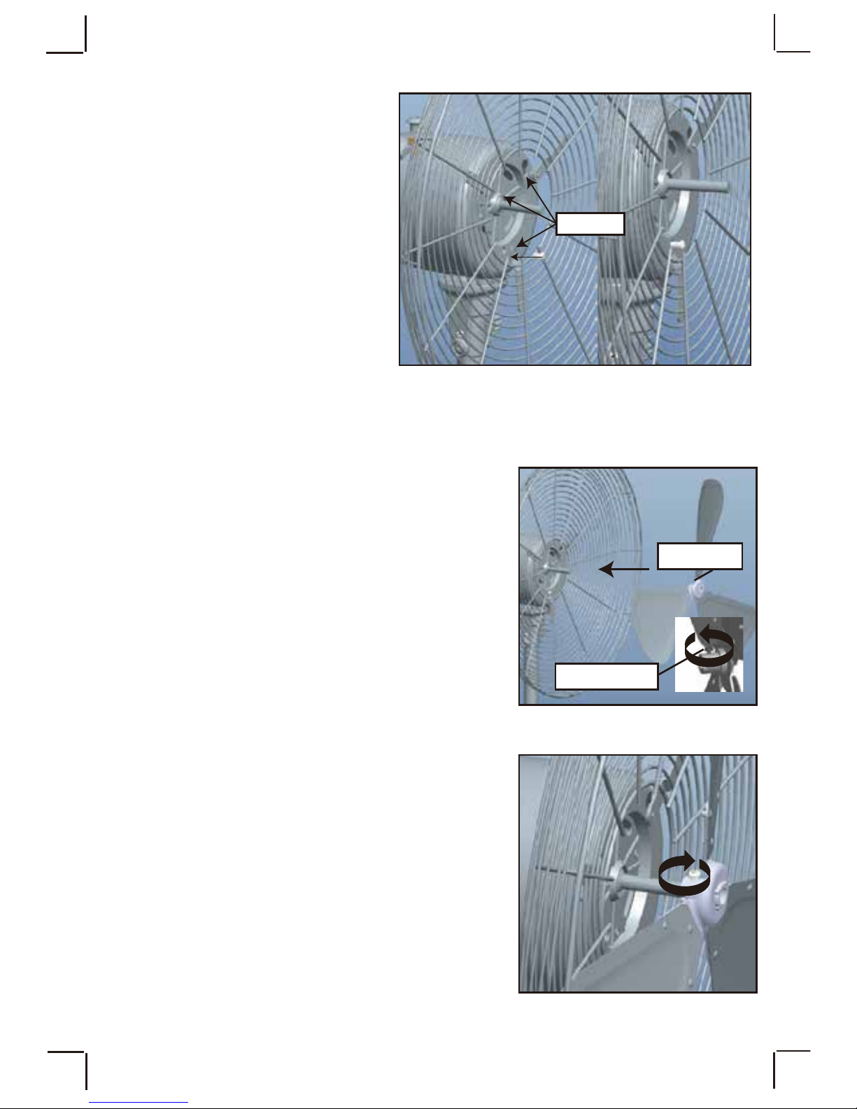
2.Place the Back Grille against
the motor housing ,insert the
two upper Buckles into the
Buckle Holes, then slide them
down to the small holes with a
little force.
Align the bottom buckle with
the screw hole, then tighten the
Screw to secure the Back Grille
to the motor . Figure 10
3.Remove the plastic sleeve from the motor
shaft. Loosen the screw at the back of
the Fan Blade,and slide the Fan Blade onto
the motor shaft. Figure 11.
4.Retighten the Screw on the blade assembly
to secure it to the motor shaft. Make sure that
the end of the screw is positioned within the
flat notch on the shaft. Figure 12.
Figure 10.
Figure 12.
7
Buckles
Figure 11.
Blade screw
Front side

5. Remove the Grille Ring from the Front
Grille by loosening the Screw holding it.
6. Place the Front Grille against the Back
Grille and push them together until the tabs
on the grilles hold them together.Figure 13.
7.Slide the Grille Ring over both Front and Back Grilles ,turning the ring so
that the Screw that secures it, is on the bottom. Figure 14-15.
8.Retighten the Screw to secure the Grille Ring
over the Front and Back Grilles. Figure 16.
Figure 13.
8
Figure 15.
Figure 16.
Grille screw
Tabs
Figure 14.
Grille ring
Screw
Grille Ring

OPERATION
OFF/SPEED SELECTION
The power switch is incorporated in the speed control switch on the top of the fan motor.
0- The Fan is switched Off
1- The Fan operates at the lowest speed
2- The Fan operates at the medium speed.
3- The Fan operates at the highest speed.
Figure 17
OSCILLATION
To allow the fan to oscillate, push the Knob down.
Pull up on the knob if oscillation is not desired. Figure 18
FAN HEAD ADJUSTMENT
To adjust the angle of the fan head.
1. Loosen the tilt adjustment knob under the Fan Motor.
2. Adjust the fan to the angle desired and retighten the
knob to secure the fan at that angle. Figure 19
Figure 17.
Figure 18.
Figure 19.
9
Switch
Adjustment knob
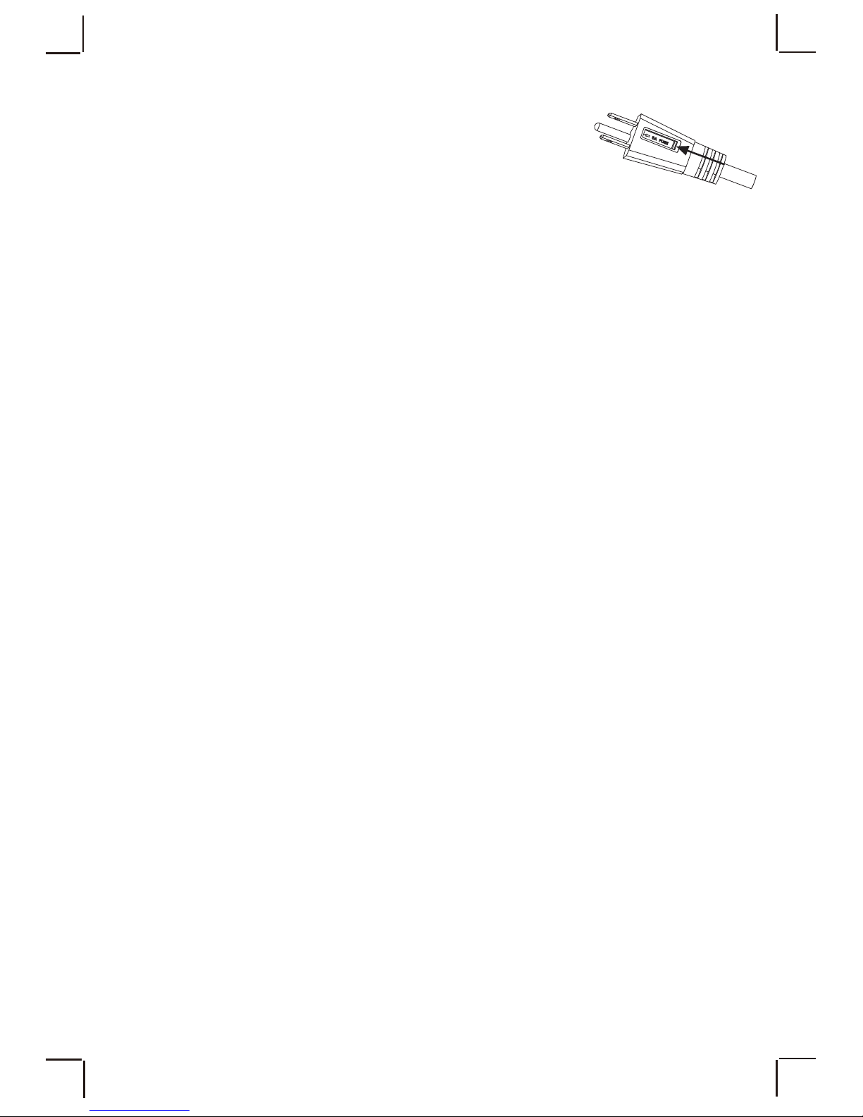
USER SERVICING INSTRUCTIONS
a) Grasp the plug and remove it from the receptacle or other
outlet device. Do not unplug by pulling on the cord.
b) Open the fuse cover. Slide open the fuse access cover on
top of attachment plug towards blades.
c) Remove the fuse carefully. Push the fuse from the other side or turn the fuse holder
over to remove the fuse.
d)Risk of fire. Replace the fuse only with 5A, 125 Volt fuse.
e) Close the fuse cover. Slide closed the fuse access cover on top of the attachment plug.
f) Risk of fire. Do not replace attachment plug which contains a safety device(fuse)
that should not be removed. Discard product if the attachment plug is damaged.
Notice
1. When you replace fuse, please don’t operate suddenly or overexert, or else the
product will be damaged or cause accident.
2. When you feel it hard to be operated, please make sure you have got the right way.
CLEANING AND MAINTENANCE
1. Always unplug the fan before cleaning,disassembly or servicing.
2. Use only a soft,damp cloth to gently wipe the outer surface of the fan.
3. To clean between the grilles, we recommend using a pipe cleaner, flexible
dustwand, vacuum cleaner or compressed air to gently remove the dust.
4. DO NOT immerse the fan in water and never allow water to drip into the motor
housing.
5. Be sure to use a soft cloth moistened with a mild soap solution.
PRINTED IN CHINA
When storing your fan in the off season, it is important to keep it in a safe dry location.
It is important to protect the fan head from dust. WE STRONGLY RECOMMEND
USING THE ORIGINAL BOX FROM PURCHASE.
FAN STORAGE
10
Inhaltsverzeichnis
Sprachen:
Andere Cozy Breeze Lüfter Handbücher


