D&B D80 Bedienungsanleitung

DD80
Manual 1.8 en

S
y
m
b
o
l
s
o
n
t
h
e
p
r
o
d
u
c
t
P
l
e
a
s
e
r
e
f
e
r
t
o
t
h
e
i
n
f
o
r
m
a
t
i
o
n
i
n
t
h
e
m
a
n
u
a
l
.
W
A
R
N
I
N
G
!
D
a
n
g
e
r
o
u
s
v
o
l
t
a
g
e
!
General information
D80 Manual
Version: 1.8 en, 03/2015, D2020.EN .01
Copyright © 2015 by d&b audiotechnik GmbH; all rights
reserved.
Keep this manual with the product or in a safe place
so that it is available for future reference.
We recommend you to regularly check the d&b website for the
latest version of this manual.
When reselling this product, hand over this manual to the new
customer.
If you supply d&b products, please draw the attention of your
customers to this manual. Enclose the relevant manuals with the
systems. If you require additional manuals for this purpose, you
can order them from d&b.
d&b audiotechnik GmbH
Eugen-Adolff-Strasse 134, D-71522 Backnang, Germany
T +49-7191-9669-0, F +49-7191-95 00 00
[email protected], www.dbaudio.com

Explanation of graphical symbols
The lightning symbol within a triangle is intended to alert
the user to the presence of uninsulated "dangerous
voltages" within the unit’s chassis that may be of
sufficient magnitude to constitute a risk of electric shock
to humans.
The exclamation point within a triangle is intended to
alert the user to the presence of important operating and
service instructions in the literature accompanying the
product.
Before using this product, carefully read the
applicable items of the following safety instructions.
1. Keep these instructions for future reference.
2. Read these instructions.
3. Heed all warnings.
4. Follow all instructions.
5. Keep water or other liquids away from the unit. Do not place
liquid filled containers, for example beverages, on top of the
unit.
6. Do not operate the unit while it is wet or standing in liquid.
7. Always operate the unit with the chassis ground wire
connected to the electrical safety earth. Do not defeat the
safety purpose of a grounding-type plug. A grounding-type
plug has two blades and a third grounding prong. The third
prong is provided for your safety. If the provided plug does
not fit into your outlet, consult an electrician for replacement of
the obsolete outlet.
8. Do not use this unit if the power cord is damaged or frayed.
Protect the power cord from being walked upon or pinched,
particularly at the plugs and the point where it exits from the
apparatus.
9. The unit is intended for use in a 19" rack. Follow the mounting
instructions. When a rack on wheels is used, exercise caution
when moving the loaded rack to avoid injury from tipping
over.
10. Unplug this apparatus during lightning storms or when unused
for long periods of time.
11. Never connect an output pin to any other amplifier input or
output pin or to the earth (ground). This may damage the unit
or lead to electric shock.
12. Lay all cables connected to the unit carefully so that they
cannot be crushed by vehicles or other equipment and that no
one can either step on them or trip over them.
13. Refer all servicing to qualified service personnel. Servicing is
required when the apparatus has been damaged in any way
such as:
– Power-supply cord or plug is damaged.
– Liquid has been spilled into the unit.
– An object has fallen into the unit.
– The unit has been exposed to rain or moisture.
– The unit does not operate normally.
– The unit was dropped or the chassis is damaged.
– Do not remove top or bottom covers. Removal of the covers
will expose hazardous voltages. There are no user
serviceable parts inside and removal may void the warranty.
14. Use the mains plug as the disconnecting device and keep it
readily accessible. If the mains plug is not readily accessible
due to mounting in a 19" rack, then the mains plug for the
entire rack must be readily accessible.
15. An experienced user must always supervise the equipment,
especially if inexperienced adults or minors are using the
equipment.
IMPORTANT SAFETY INSTRUCTIONS
d&b D80 Manual 1.8 en 3

1. Introduction....................................................................... 6
1.1. Intended use................................................................ 6
1.2. D80 Concept............................................................... 6
2. Technical specifications................................................. 8
3. Scope of supply............................................................. 10
4. Startup.............................................................................. 11
4.1. Overview................................................................... 11
4.2. Rack mounting and cooling...................................... 12
4.3. Connections............................................................... 14
4.3.1. Mains connection.................................................. 14
4.3.2. Audio INPUT and LINK connectors..................... 16
4.3.3. Output connectors................................................. 17
4.3.4. ETHERNET (Dual Ethernet port)............................ 18
4.3.5. CAN (CAN-Bus).................................................... 19
4.4. Controls and indicators............................................ 20
4.4.1. Mains power switch.............................................. 20
4.4.2. Display - User interface......................................... 20
4.4.3. Standby mode....................................................... 21
4.4.4. Mute functions....................................................... 22
5. User interface................................................................. 23
5.1. Operating concept................................................... 23
5.2. Screen layout and conventions................................ 24
5.3. Screen items and views............................................ 24
5.3.1. Function buttons..................................................... 24
5.3.2. Navigation buttons................................................ 24
5.3.3. Input fields.............................................................. 25
5.3.4. Input masks............................................................ 25
5.3.5. Information fields................................................... 25
6. Home screen................................................................... 26
6.1. Header area - Device............................................... 27
6.2. Data area - Channel strip(s)..................................... 27
7. Channel strip.................................................................. 28
8. Basic settings - Quick reference.............................. 30
9. Device setup................................................................... 32
9.1. Device name............................................................. 33
9.2. Input........................................................................... 34
9.2.1. Input mode............................................................. 34
9.3. Output........................................................................ 36
9.3.1. Output mode.......................................................... 37
9.4. Remote....................................................................... 41
9.4.1. Remote ID............................................................... 41
9.4.2. Ethernet settings..................................................... 41
9.5. More.......................................................................... 42
9.5.1. Preferences............................................................. 42
9.5.1.1. Display................................................................ 43
9.5.1.2. Lock..................................................................... 43
9.5.1.3. Preferences/More.............................................. 45
Contents
d&b D80 Manual 1.8 en4

9.5.1.3.1. System reset.................................................... 46
9.5.2. Info......................................................................... 46
9.5.3. Levels...................................................................... 47
9.5.4. Mains current limiter (MCL).................................. 48
9.5.5. Scope..................................................................... 49
10. Channel setup................................................................ 50
10.1. Channel name........................................................ 51
10.2. Configuration switches - Filter_1, _2, _3.............. 52
10.3. Level......................................................................... 52
10.4. EQ - Equalizer ........................................................ 52
10.5. DLY - Delay............................................................. 55
10.6. Input routing............................................................ 55
10.7. System check.......................................................... 56
10.8. Speaker................................................................... 57
10.8.1. LINEAR setup....................................................... 59
10.8.2. LoadMatch.......................................................... 60
10.9. Frequency generator - Freq. gen........................... 61
11. Web Remote interface................................................ 62
12. Operation (Hardware references)........................ 65
12.1. Power supply.......................................................... 65
12.1.1. Active Power Factor Correction (PFC)............... 65
12.1.2. Automatic mains range selection....................... 65
12.1.3. Mains voltage monitoring................................... 65
12.1.4. Mains inrush current limiter................................. 66
12.1.5. Mains supply requirements................................ 66
12.1.6. Generator operation/UPS requirements........... 67
12.2. Power amplifiers..................................................... 67
12.3. Cooling fans............................................................ 68
12.4. Current/power draw and thermal dissipation...... 68
13. Service/Maintenance and care.............................. 70
13.1. Service..................................................................... 70
13.2. Maintenance and care.......................................... 70
13.2.1. Touch screen cleaning........................................ 70
13.2.2. Touch screen calibration..................................... 71
14. Manufacturer's Declarations................................... 72
14.1. EU declaration of conformity (CE symbol)........... 72
14.2. WEEE Declaration (Disposal)................................ 72
14.3. Licenses and Copyright.......................................... 72
15. Appendix......................................................................... 73
15.1. System check - References..................................... 73
15.2. Error messages....................................................... 75
d&b D80 Manual 1.8 en 5
1.1. Intended use
The d&b D80 amplifier is designed for mobile applications and
intended to be used with all current d&b loudspeakers. A LINEAR
setup is available allowing the D80 to be used as a linear power
amplifier.
NOTICE!
The device complies with the electromagnetic compatibility
requirements of EN 55103 (product family standard for audio,
video, audio-visual and entertainment lighting control apparatus for
professional use) for the environments E1 (residential), E2 (business
and commercial), E3 (outdoor use in urban areas) and E4
(outdoor use in rural areas).
Acoustic interference and malfunctions may occur if the unit is
operated in the immediate vicinity of high-frequency transmitters
(e.g. wireless microphones, mobile phones, etc.). Damage to the
device is unlikely, but cannot be excluded.
1.2. D80 Concept
The D80 amplifier represents the next generation of high power
four channel Class D amplifiers. It is developed and manufactured
by d&b using Digital Signal Processing (DSP) to incorporate
loudspeaker specific configurations and user definable setups,
equalization and delay functions. The amplifier is designed to fully
drive all d&b loudspeakers and provide comprehensive
management and protection capabilities. This high performance
amplifier provides the power density required for both touring and
installation purposes while the powerful signal processing extends
the level of functionality of the on-board features.
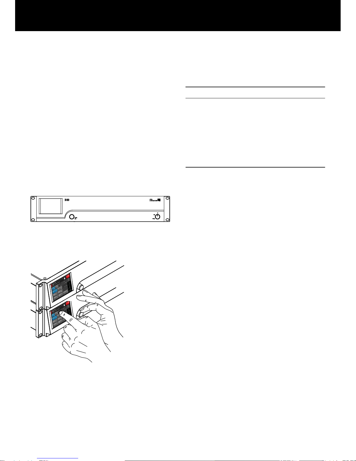
The user interface of the amplifier consists of two elements: a color
TFT touch screen providing visual information and quick access to
the amplifier settings and a rotary encoder on the front panel for
data input purposes. To allow ease of operation when the amplifier
is below eye level, the front panel and the integrated display are
tilted upwards. As a result, the front panels of multiple amplifiers on
top of each other within a rack integrate to form one large control
surface.
The user definable equalizer features two independent 16-band
EQ groups within each channel. These provide parametric, notch,
shelving and asymmetric filters as well as a graphic EQ (via the
d&b R1 Remote control software V2) allowing instant switching
between two EQ curves for comparison. The delay capability
covers a range of up to 10 s. All loudspeaker specific functions
such as CUT, HFA, HFC, CSA or CPL are available. The DSP unit of
the amplifier has a fixed latency of 0.3 ms.
D80 Front view
D80 User interface
1. Introduction
d&b D80 Manual 1.8 en6

The amplifier enables up to four input channels, which may be four
analog inputs, two analog and two AES channels or four AES
channels. Each input channel can be routed to any of the output
channels A to D. XLR connectors 2 and 4 of the D80 can be used
as either digital or analog inputs, connectors 1 and 3 are analog
inputs. Link outputs are supplied for all inputs. This 1:1 ratio of
inputs to amplifier output channels increases flexibility of
application, particularly for use as monitor, frontfill or effect
channels.
The D80 amplifier outputs are optionally NL4 or EP5 connectors
plus one centered NL8 connector with all pins driven. The latter
serves as an interface to a rack panel or to loudspeaker multicores
and breakout adapters. To simplify configuration, the output mode
of the amplifier can be configured like a set of two dual channel
amplifiers providing Dual Channel, Mix TOP/SUB or 2-Way Active
modes for the left and the right channels A/B and C/D,
respectively.
For applicable loudspeakers, d&b LoadMatch enables the D80
amplifier to electrically compensate for the properties of the cable
used to connect the loudspeakers to the amplifier output. This
function which covers a bandwidth of up to 20 kHz preserves the
tonal balance when cable lengths of up to 70 m (230 ft) are used.
Due to its design LoadMatch does not require additional wires and
is therefore applicable with any connector type used.
To provide optimum compensation, cable length and cross-
sectional data as well as the number of loudspeakers connected to
the amplifier channel can be entered on the amplifier.
The D80 utilizes a switch mode power supply with active Power
Factor Correction (PFC) to produce a clean current draw and
ensure stable and efficient performance under adverse mains
conditions. The high power capabilities provide increased power
to fully drive all current d&b loudspeaker cabinets and sufficient
headroom for any future systems.
Remote control and full system integration are realized using the
d&b ArrayCalc simulation software and R1 Remote control
software V2. The D80 amplifier includes two Ethernet ports on
etherCON connectors to enable daisy chaining. Both Ethernet and
dbCAN protocols are incorporated. The Ethernet protocol
implemented in the d&b R1 Remote control software V2 and the
D80 amplifier is a protocol developed by the OCA Alliance (Open
Control Architecture Alliance), of which d&b is a founding member.
For further details, please refer to the OCA website:
www.oca-alliance.com.
D80 Rear view
d&b D80 Manual 1.8 en 7

Audio data (linear setting with subsonic filter)
Maximum output power per channel (THD + N < 0.5%, all channels
driven)
CF = 6 dB @ 4/8 ohms 4 x 2600/2000 W
CF = 12 dB @ 4/8 ohms 4 x 4000/2000 W
Maximum output voltage 180 V
Frequency response (—1 dB) 35 Hz – 20 kHz
THD+N 20 Hz – 20 kHz, 600 W @ 4 ohms) < 0.5%
S/N ratio (unweighted, RMS)
Analog input > 110 dBr
Digital input > 114 dBr
Damping factor (20 Hz – 200 Hz into 4 ohms) > 100
Crosstalk (20 Hz – 20 kHz) < –70 dBr
Gain (Linear mode @ 0 dB) 31 dB
Protection circuits
Mains inrush current limiter 13 A RMS @ 230 V AC
22 A RMS @ 120 V AC
27 A RMS @ 100 V AC
Ground fault protection
Output current limitation/protection 65 A / 75 A
Output DC offset protection 10 V
Output HF Voltage Limiter 60 V @ 10 kHz
Output pop-noise suppression
Mains Current Limitation (MCL) 95 to 50 % of 16 / 30 A
Overvoltage protection Up to 400 V AC
Self-resetting overtemperature protection
Power supply
Autosensing switched mode power supply with active power factor
correction (PFC)
Mains connector powerCON-HC
Rated mains voltage 208 to 240 V, 50 – 60 Hz
high range
100 to 127 V, 50 – 60 Hz
low range
Mains fuse internal
Power consumption (typical values)
Standby 9 W
Idle 180 W
Max. power consumption (short term RMS) 7000 W
Audio input connectors
INPUT analog (A1 - A4) 3 pin XLR female
Pin assignment 1 = GND, 2 = pos., 3 = neg.
Input impedance 38 kOhms, electronically balanced
Common mode rejection (CMRR @ 100 Hz/10 kHz) > 70 / 50 dB
Maximum input level (balanced/unbalanced) +25 / 17 dBu
+27 dBu @ 0 dBFS
LINK analog (A1 - A4) 3 pin XLR male
Pin assignment 1 = GND, 2 = pos., 3 = neg.
parallel to input
INPUT digital (D1/2, D3/4) 3 pin XLR female, AES 3
Pin assignment 1 = GND, 2 = AES Signal, 3 = AES Signal
Input impedance 110 ohms, transformer balanced
Sampling 48 / 96 kHz / 2 Ch/n
Synchronization Word-Sync: PLL-locked to source (slave mode)
LINK digital (Output) 3 pin XLR male
electronically balanced
analog signal buffering (refresh), power fail relay (Bypass)
Output connectors
SPEAKER OUTPUTS A/B/C/D 4 x NL4
optional: 4 x EP5
4 CHANNEL OUTPUT 1 x NL8
Network connectors
CAN 2 x RJ 45 parallel
ETHERNET 2 x etherCON®
Dual Ethernet port with built-in 2-port Ethernet switch
10/100 Mbit
Controls and indicators
POWER Mains power switch
SCROLL/EDIT Digital rotary encoder
Display TFT color touch screen, 3.5" / 320 x 240 Pixel
2. Technical specifications
d&b D80 Manual 1.8 en8

Digital Signal Processing
System start-up time 17 sec.
Sampling rate 96 kHz / 27 Bit ADC / 24 Bit DAC
Latency analog input 0.3 msec.
Latency digital input (AES) 0.3 msec.
48 kHz / 96 kHz
Input dynamic > 127 dB
ADC dynamic > 110 dB
DAC dynamic > 110 dB
Equalizer two user definable 16-band equalizers
Filter types: PEQ/Notch/HiShlv/LoShlv/Asym
Delay 0.3 msec. - 10 sec.
Frequency generator Pink noise or Sine wave 10 Hz – 20 kHz
Operating conditions
Temperature range* –10 °C ... +40 °C / +14 °F ... +104 °F
*continuous operation
Temperature range** –10 °C ... +50 °C / +14 °F ... +122 °F
**reduced output power or short term operation
Storage temperature –20 °C ... +70 °C / –4 °F ... +158 °F
Humidity (rel.), long term average 70%
Fan noise emission
Rack mounted, measured on axis, 1 m to front panel, A-weighting
Idle 34 dB(A)
Ambient temperature 22 °C / 71.6 °F
Max. RPM 49 dB(A)
Dimensions and weight
Height x width x depth 2 RU x 19" x 530.5 mm
2 RU x 19" x 20.9"
Weight 19 kg / 42 lb
D80 enclosure dimensions in mm [inch]
d&b D80 Manual 1.8 en 9

Before starting up the device, please verify the shipment for
completeness and proper condition of the items.
If there is any sign of obvious damage to the unit and/or the
power cord, do not operate the unit and contact your local dealer
from whom you received it.
Pos. Qty. d&b Code Description
[1] 1 Z2710 d&b D80 Amplifier, dependent on chosen output option (NL4 or EP5 output
connectors).
Including:
[2] 1 Z2620.xxx Power cord D80 (specific to country).
[3] 1 K6007.050 RJ 45 Patch cable, 0.5 m (1.6 ft) CAT 6/AWG 24-STP (shielded twisted pair) to be
used for daisy chaining multiple amplifiers within a rack.
[4] 1 Z6116 RJ 45 M Terminator for terminating the last device of a CAN-Bus segment.
[5] 1 D2020.EN .01 D80 Manual.
3. Scope of supply
d&b D80 Manual 1.8 en10
Inhaltsverzeichnis
Andere D&B Verstärker Handbücher


