DEMON ELECTRIC PILOT Bedienungsanleitung

Pilot
Installation Manual
Scan to watch
assembly video

OWNER’S MANUAL
Table of contents
First of all, we would like to thank you for choosing the Pilot electric bike.
We warmly welcome you to our Demon Electric family. We wish you enjoy the numerous kilometers and
happy moments with your new bike.
After the initial shipment we have made many improvements and modifications for the Pilot including:
•
•
•
•
•
Suspended seat post - Takes the shock out of the big bumps, without the cost or complexity of suspension.
Adjustable handlebar stem- Provides up to 1 1/2” of rise and reach adjustment, for fully customizable
riding position.
Upgraded Shimano derailleur- Rigid cast aluminum construction gives smoother, more precise shifting.
New gearing, with taller top gear for relaxed touring, plus a lower low gear for tight, technical riding.
Demon Electric E-Bikes can be upgraded with additional accessories, such as water bottle holders, phone
mounts, etc.
ASSEMBLY INSTRUCTIONS ......................................................................................3
INSTALL FRONT FORK...................................................................................................4
INSTALL STEM...................................................................................................................5
INSTALL FRONT WHEEL ..............................................................................................6
INSTALL HANDLEBAR ...................................................................................................7
INSTALL SEAT POST........................................................................................................8
INSTALL PEDAL..................................................................................................................9
INSTALL FRONT FENDER AND REFLECTOR........................................................10
INSTALL BATTERY.............................................................................................................11
FOLDING THE BIKE..........................................................................................................12
OPERATING INSTRUCTIONS ......................................................................................13
DISPLAY INSTRUMENT SETTINGS..........................................................................14
TROUBLESHOOTING.......................................................................................................15
WARNINGS AND SAFETY.............................................................................................17

BELOW ARE THE GUIDELINES FOR THE INITIAL
BATTERY CHARGING PROCESS:
• Before using the e-bike for the first time, we strongly recommend that you conduct a preliminary battery
check-up and perform a full charge for optimal performance.
• To charge the battery, before riding connect the e-bike to the charger and allow the battery to reach full
capacity. According to the manufacturer’s instructions, the initial charge typically takes between 48 to 72
hours prior to your first ride.
• During the charging process, keep an eye on the LED indicator or display on your battery charger. This will
give you insights into the charging progression. If you encounter any problems, don’t hesitate to reach out to
the manufacturer for assistance.
• After the battery has been fully charged, it’s recommended to take your e-bike out for a test ride. Pay at-
tention to its performance, including the speed, range, and power-assistance levels. Any significant discrep-
ancies might imply that the battery capacity is compromised and needs further attention.
• Even when the e-bike is not being used frequently, it’s crucial to regularly charge and discharge the bat-
tery. This practice helps to prevent battery degradation during periods of storage.

2
Pilot Manual |
IMPORTANT
Electric Bikes can be dangerous to use. The user or consumer assumes all risk of personal injuries, damage,
or failure of the bicycle or system and all other losses or damages to themselves and others and to any
property arising as a result of using the bicycle.
As with all mechanical components, the bicycle is subjected to wear and high stresses. Different materials
and components may react to wear or stress fatigue in different ways.
If the design life of a component has been exceeded, it may suddenly fail possibly causing injuries to the
rider. Any form of crack, scratches or change of coloring in highly stressed areas indicate that the life of the
component has been reached and it should be replaced.
Please do not hesitate to contact us. If any problems may occur, please email us at
customersuppor[email protected] for any customer service solutions such as replacement parts, technical
information, and any other issues.
All new E-Bike purchases come with a 2-year warranty, the warranty card must be filled in and
registered in order to qualify for warranty.
For any other commercial or general inquires please contact Demon Powersports at 905 881 9510 or
DO NOT DISASSEMBLE, MODIFY OR
REPLACE ELECTRICAL PARTS.
PLEASE NOTE: THIS MANUAL IS NOT INTENDED
AS A DETAILED USER, SERVICE, REPAIR OR
MAINTENANCE MANUAL. PLEASE SEEK
ASSISTANCE FROM A QUALIFIED TECHNICIAN FOR
SERVICE, REPAIRS OR MAINTENANCE.

3
Pilot Manual |
ASSEMBLY INSTRUCTIONS
Your bike has been pre-assembled and requires only a few simple steps to get it ready for you to ride:
Remove the outside carton after cutting the nylon bands. Remove all the inside cardboard protection and
bubble wrap. Carefully remove your bike from the carton and gently rest it in place. Be careful not to cut
any wires when cutting the zip ties.
Remove brake pad holders when installing, avoid squeezing the brakes when removing the pad holder.
Ensure the following pieces are included in the package. If there are any missing parts, please contact
Demon for help replacing missing pieces.

4
Pilot Manual |
INSTALL FRONT FORK
Remove the bolts on the top of the front fork, and remove two rings and a plastic cover, and place them in
order. Insert the front fork into the frame, pay attention to the wiring harness. As shown in the picture, they
need to be placed to prevent the wire harness from being entangled.
Place the small ring first, the big ring second (Figure 2-4), and press them to the Bottom.

5
Pilot Manual |
STEM INSTALLATION
Locate the stem, loosen the two screws on the bottom side, but do not remove. Mount
the stem into the front fork (Note: The two screws just loosened should be on the bike’s passenger
side). Open the folding handle.
Method: There is a small spherical handle on the side of the handle, pull it to the top, and then pull
the handle outward. Fold the stem, and place the plastic cover into it. Tighten the screws,
and restore the stem to its original state.
6
Pilot Manual |
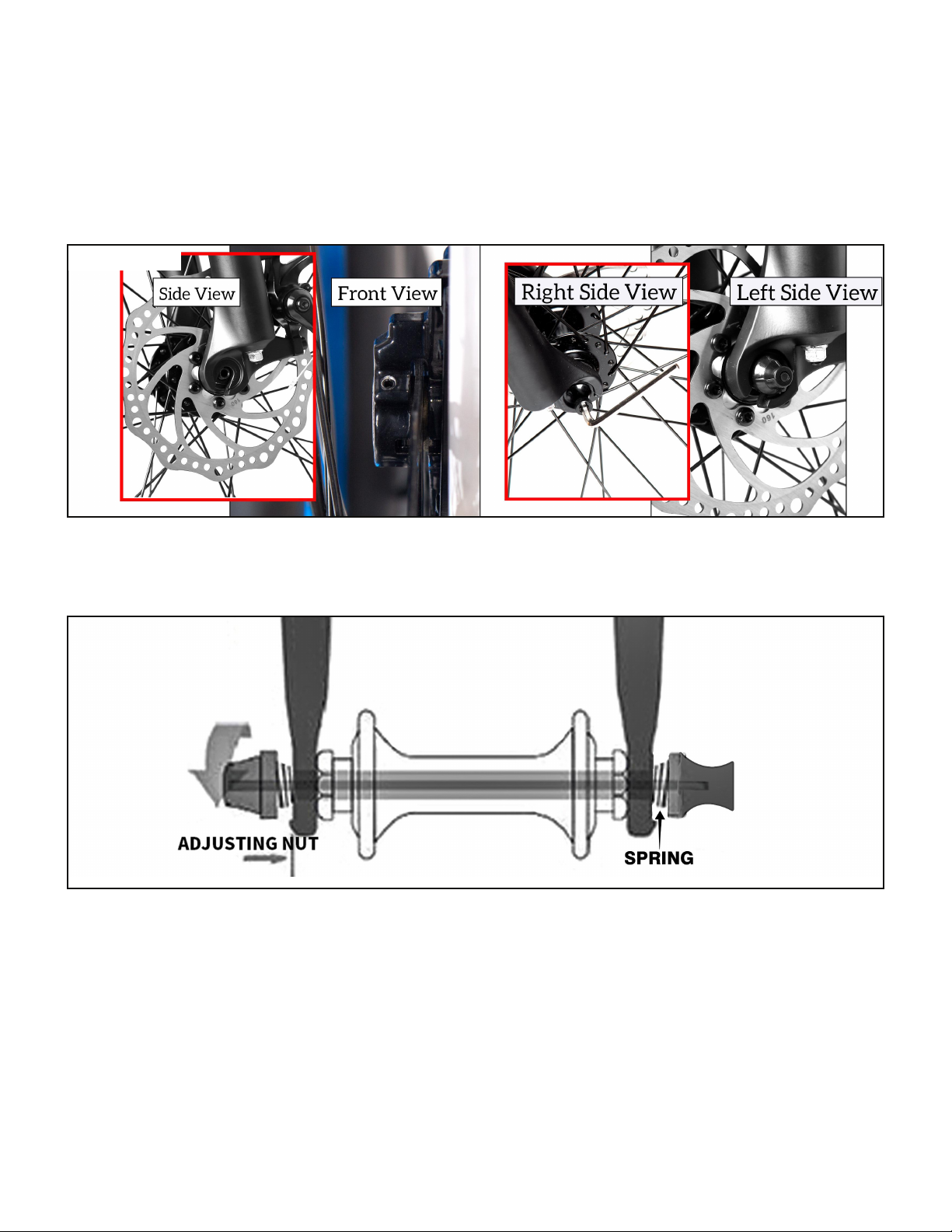
FRONT WHEEL INSTALLATION
Locate the front wheel, pull out the rubber protection pad, and remove the quick release axle tied to
the spokes. Lift the front fork, and insert the front wheel between the fork blades so that the axle seats
firmly at the top of the fork dropouts. (Push the wheel firmly to the top of the slots in the fork dropouts,
and center the wheel rim in the fork at the same time). Note: The front fork should set on the thread of
the front wheel axle. The disc brake rotor should locate in the center of the brake pad.
Insert the quick release axle (Note: The small spring heads face the center and one on each side of
the wheel). Use the Allen Wrench to tighten the nut of the quick release.

7
Pilot Manual |
HANDLEBAR INSTALLATION
Locate the cam lever on the top of the stem, open the cam lever, loosen the nut, and remove the cam lever,
slide out the metal cover. Place the handlebar into the groove on the top of the stem, slide the metal cover
back into the stem. Adjust the handlebar to a proper angle that fits you, and tighten the handlebar with the
cam lever.
The handlebar must keep parallel with the front fork after the handlebar is installed, and the stem should
be slightly tilted forward and tighten the two screws that were loosened before. Adjust the handlebar’s
height to the position fit you the best, and please note the min insertion line should not be out of the tube.
WARNING: It may cause the stem tube to rupture and cause a serious accident if the min insertion line is
out of the tube. The customer is responsible for accidents caused by improper installation.

8
Pilot Manual |
SEAT POST INSTALLATION
Please pay attention to the vertical lines on the seat post; it is the minimum insert line or safety line.
Please make sure install the post into the frame deeper than the minimum insertion line. It is at the bottom
of the seat post.
Warning: It could break the seat tube during riding if the seat post does not install correctly. It is not
covered by the warranty.
Open the clamp on the seat tube, insert the seat post into the seat tube, adjust the seat to a comfortable
height, tighten the tension adjusting nut, and press the clamp lever inward toward the seat tube.
Warning: The cam lever may be bent if over tighten tension nut when the cam lever un-clamped. It is
not covered by warranty.
Please Note: If necessary, tighten the clamp by twisting the clamp handle clockwise while in the
un-clamped position. Then, fold the handle in toward the seat post. This should require a fair amount
of force to ensure the seat post is held tight. If necessary, the clamp can be further tightened with a 5
mm Allen wrench while in the clamped position.
Inhaltsverzeichnis
Andere DEMON ELECTRIC Fahrrad Handbücher

DEMON ELECTRIC
DEMON ELECTRIC THUNDERBOLT SL Bedienungsanleitung

DEMON ELECTRIC
DEMON ELECTRIC REBEL Bedienungsanleitung

DEMON ELECTRIC
DEMON ELECTRIC PHANTOM Bedienungsanleitung

DEMON ELECTRIC
DEMON ELECTRIC OUTLAW Bedienungsanleitung

DEMON ELECTRIC
DEMON ELECTRIC 6IX Bedienungsanleitung

DEMON ELECTRIC
DEMON ELECTRIC TRONIO Bedienungsanleitung

DEMON ELECTRIC
DEMON ELECTRIC BLACKTAIL Bedienungsanleitung

DEMON ELECTRIC
DEMON ELECTRIC ARGO Bedienungsanleitung

DEMON ELECTRIC
DEMON ELECTRIC ESCAPE Bedienungsanleitung


