Detectors Incorporated D390 Bedienungsanleitung

MAN‐D390‐0001
1
INSTRUCTION MANUAL
Detectors Incorporated
Model D390
Flame Detector

MAN‐D390‐0001
2
TableofContents
INTRODUCTION……………………………………………………………… 3
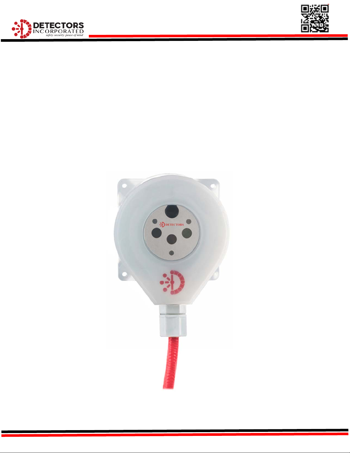
Productdescription…………………………………………………………. 3
Specifications………………………………………………………............. 4
General……………………………………………………………………………. 4
Electrical………………………………………………………………………….. 4
Environmental…………………………………………………………………. 4
Mechanical………………………………………………………………………. 4
INSTALLATION…………………………………………………………………. 5
DetectorDimensions……………………………………………………….. 5
MountingtheDetector……………………………………………………. 5
Positioning………………………………………………………………………. 5
DirectMounting………………………………………………………………. 5
InstallationTips……………………………………………………………….. 5
DetectorConfiguration……………………………………………………. 6
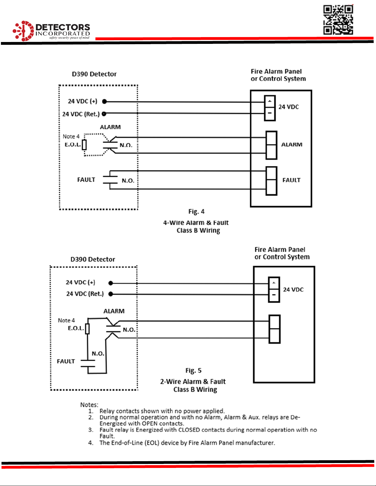
DetectorWiring……………………………………………………………….6‐11
OPERATIONANDSTARTUP……………………………………………… 12
DetectorPerformanceandResponse………………………………. 12
DetectorOperation………………………………………………………….. 12
DetectorVisualStatusIndication……………………………………… 12
NormalOperation……………………………………………………………. 12
ALARMOperation…………………………………………………………….12‐13
FaultOperation……………………………………………………………….. 13
DetectorSelf‐Test……………………………………………………………. 14
DetectorOpticalPathTest………………………………………………. 14
MAINTAINANCE………………………………………………………………. 14
InspectionandCleaning…………………………………………………… 14
PeriodicTesting……………………………………………………………….. 14
TROUBLESHOOTING……………………………………………….. 15
EVENTLOG……………………………………………………………… 15
ACCESSORIES………………………………………………………….. 15
PRODUCTSUPPORT……………………………………………….. 15
TechnicalSupportandCustomerSupport………………. 15
WARRANTY……………………………………………………………. 16
APPENDIX“A”
ORDERINGINFORMATION…………………………………….. 17
APPENDIX“B”………………………………………………………… 18

MAN‐D390‐0001
3
1.0 Introduction
1.1 ProductDescription
The Multi‐Spectrum D390 is a stand‐alone 3IR flame detector designed
specificallyforinstallationinSemiconductorcleanroomsandwetbenches
forfastdetectionofHydrocarbonandNon‐Hydrocarbonbasedfires.The
ModelD390sensestheIRradiationin3discretebandsofInfraredinthe
rangeof2‐5microns.
The Model D390 sensors and electronic circuit boards are enclosed in a
sealedwater‐tightPolypropyleneenclosureratedIP67makingitanideal
detectorforinstallinginharshchemicalladenenvironment.Thedetector
canbeusedasastand‐alonedeviceorcanbeinterfacedwithanyapproved
firealarmpanel.Thedetectorwillrespondtoonesquare‐footn‐Heptane
firewithin3‐5secondsfromof30feet.

MAN‐D390‐0001
4
1.2 Specifications
1.2.1 General
Field‐of‐View: 90°Horizontal&Vertical
SpectralSensitivity: IR: 2‐5microns(3discretebands)
ResponseTime: 3‐5Seconds
DetectionRange: 1’x1’n‐Heptanefire:30feet
32”Hydrogenplume(3/8”orifice):20feet
1.2.2 Electrical
OperatingVoltage: 24VDCnominal(18‐31),Regulated
PowerConsumption: Standby:60mA@24VDC
Alarm:90mA@24VDC
RelaysOutputs: Alarm&AuxiliaryRelays:
SPDT—contactsrated2A@24VDC
De‐EnergizedwithN.O.contacts(powerapplied)
Faultrelay:
SPST–contactrated2A@24VDC
EnergizedwithClosedcontact(powerapplied)
AnalogOutput: 0‐20mAStepped‐Source
Communication: RS485ModBus
VisualIndications: GreenLED‐Normal
RedLED‐Alarm
AmberLED‐Fault
Wiring Integralmulti‐conductorcableharness
withTeflonJacket
20AWG15‐conductorcable,20’long
1.2.3 Environmental
HumidityRange: 5to95%relativehumidity,non‐Condensing
TemperatureRange: ‐40to+185°F(‐40to+85°C)
EnclosureType: NEMA4,IP67
1.2.4 Mechanical
EnclosureMaterial: Polypropylene,sealed
Weight: 1.5lbs.(0.7kg)

MAN‐D390‐0001
5
2.0 Installation
2.1 DetectorDimensions
TheD390detectorhas(4)6mmholesintherearmountingflange(Figure1)thatcanbeusedtomount
thedetectordirectlyonaflatsurface.Thedetectorcanalsobemountedusinganoptional
Polypropyleneswivelmountingbracket(Figure2)thatallowsthedetectoradjustmentinverticalaxis.
Figure1–DetectorDimensions
2.2 MountingtheDetector
2.2.1 Positioning‐Thedetectorshouldbeinstalledsuchthatthecenterofthedetector’sfield‐of‐view
isaimeddirectlyatthecenteroftheareatobeprotected(hazardarea).Detectorsshouldbe
installedabovethehazardareapointingdownwardwithnoobstructionoftheField‐of‐View.
2.2.2 DirectMounting.‐Thedetectormayalsobemounteddirectlytoaflatsurfaceusingthe(4)
mountingholeontherearmountingflangeandsecureitfirmlywith(4)stainlesssteelscrews.
2.2.3 InstallationTips:‐Wheninstallingthedetectors,beawareofthefollowingconditions:
a) Ifdetectorsareinstalledinacompartmentcontainingchemicalbathsorheaters,care
shouldbetakennottoexceedthedetector’smaximumoperatingtemperature.
b) Field‐of‐Viewofdetectorsshouldnotbeblockedbyanyobjectsforoptimumperformance.
c) Detectorsshouldbeinstalledsuchthattherearenohighintensitylightsintheviewof
detectors.Highintensitylightsmaydiminishdetectorsensitivity.
d) Detectorsshouldbeinstalledsothattheyareeasilyaccessibleformaintenance.

MAN‐D390‐0001
6
2.3 DetectorConfiguration
2.3.1 Unlessspecifiedotherwise,theD390detectorsareshippedfactoryconfiguredasdescribedbelow,
withpowerapplied:
FireAlarmRelay: SPDT,NormallyDe‐Energized,N.O.,Non‐Latching
AuxiliaryRelay: SPDT,NormallyDe‐Energized,N.O.,Non‐Latching
FaultRelay: SPST,NormallyEnergized,N.C.,Non‐Latching
4‐20mA SteppedAnalog,Sourcing
Communication ModBusRTUProtocol
2.3.2 Allrelayswithstandardfactoryconfigurationare“Non‐Latching”.If“Latching”modeisrequired,
itmustbespecifiedwhenordering.PleaserefertoAppendix“A”forotherconfigurationoptions.
2.3.3 Maximumloopresistancefortheanalogoutputis800Ohms
2.3.4 TheD390DetectorisalsoequippedwithastandardRS485ModBuscommunicationprotocolfor
interfacingwithdevicesorcontrollersusingtheModbusstandard.TheRS485communication
protocolisalsousefulincommunicatingwithdetectorforviewingordownloadingtheEventLogs
andFireGraphsusingalaptopandtheLabVIEWprogrammingsoftware.
2.4 DetectorWiring
2.4.1 The D390 Detector is supplied with an integral multi‐conductor shielded cable with Individual
conductorscolor‐codedforeasyidentification(Table1).
2.4.2 Detector should be wired in according with the National Electrical Code (NFPA 70) Division 2
hazardous (Classified) locationwiring procedurein theUnited Statesoraccordingtothelocal
codesinothercountries,observingtherequirementsforElectricalSafety.
2.4.3 Terminate each color‐coded wire to an appropriate terminal in the Fire Alarm Panel, PLC, or
ControlSystem.Figures3‐6showsvariouswiringconfigurationsforthedetector.

MAN‐D390‐0001
7
Table1–D390DetectorWiringIdentification
Wire
Number
Wire
Color
Description
3 Red 24 VDC
(
+
)
1 Black 24 VDC
(
Return
)
8 Red/Black
A
larm Rela
y
Contact A
(
COM
)
13 Red/White
A
larm Rela
y
Contact B
(
N.O.
)
4 Green Fault Rela
y
Contact A
(
COM
)
9 Green/Black Fault Rela
y
Contact B
(
N.O.
)
5 Oran
g
e
A
uxiliar
y
Rela
y
Contact A
(
COM
)
10 Oran
g
e/Black
A
uxiliar
y
Rela
y
Contact B
(
N.O.
)
2 White ModBus RTU
(
+
)
7 White/Black ModBus RTU
(
-
)
6 Blue 4-20 mA
(
+
)
- Source
11 Blue/Black Test
12 Black/White
(
Not Used
)
14 Green/White
A
larm Rela
y
Contact A Loop Throu
g
h
(
*
)
15 Blue/White
A
larm Rela
y
Contact B Loop Throu
g
h
(
*
)
Cable
Shield
(*):LoopthroughwirescanbeusedforaddinganEnd‐of‐Lineresistortosupervisethe
Alarmrelaycontacts.

MAN‐D390‐0001
8
BasicWiringSchematics

MAN‐D390‐0001
9
TypicalDetectorWiring

MAN‐D390‐0001
10
DETECTORD390WIRINGSCHEMATIC
Inhaltsverzeichnis
Andere Detectors Incorporated Sicherheitssensor Handbücher


