DV Audio Promix 3 Bedienungsanleitung

DV Promix 3
Portable Audio Mixer
Operation Manual for Mixers with PCB V1.2
Copyright 2004
Professional Sound Corporation
Printed in the U.S.A.

2
TABLE OF CONTENTS
DESCRIPTION……………………………………………………………………………3
SAFETY WARNINGS……………………………………………………………………4
APPLICATIONS…………………………………………………………………………..4
PANEL LAYOUTS………………………………………………………………………..5-6
FUNCTIONS
INPUTS……………………………………………………………………………6-10
A. BALANCED INPUTS
B. INPUT LEVELS
C. MICROPHONE POWERING
D. LOW CUT FILTERS
E. CHANNEL GAIN
F. CHANNEL PANS
OUTPUTS………………………………………………………………………….10-13
A. BALANCED OUTPUTS
B. OUTPUTS, 3.5mm JACK
C. OUTPUT LIMITERS
D. HEADPHONE MONITOR OUTPUT
E. TAPE RETURN GAIN
METERS……………………………………………………………………………..14
A. PEAK READING METERS
POWERING………………………………………………………………………….15
A. INTERNAL POWER, ALKYLINE BATTERIES

3
B. EXTERNAL POWER
CONSTRUCTION…………………………………………………………………16-17
A. CHASSIS
B. ELECTRONIC TOPOLOGY
C. ENVIRONMENTAL OPERATION
INTERFACING……………………………………………………………………17-22
A. TO PROFESSIONAL DV CAMS (XLR CONNECTORS)
B. TO PRO-SUMER CAMCORDERS (3.5MM JACK)
C. TO WIRELESS MICROPHONES
D. INPUT SELCTION CHART
E. OUTPUT INTERFACE CHART
F. CABLE EXAMPLES
WARRANTY AND NON-WARRANTY SERVICE…………………………………22
SPECIFICATIONS…………………………………………………………………….23
DESCRIPTION
Thank you for purchasing the Professional Sound Corporation, DV Promix 3
Portable Audio Mixer. Professional Sound Corporation has been building
professional audio equipment for the film and television industries since 1986.
Our focus has always been on providing high quality portable audio equipment
that meets the demanding needs of our customers. Our broadcast line of
equipment has been used world-wide on feature film productions,
documentaries, television situation comedies, news gathering of all types, radio
remotes, sports coverage, Olympic events and more. We formed the “DV Audio”
line of equipment in order to offer our expertise in field audio to the DV cam
industry.

4
PSC is confident that this new DV Promix 3 Mixer has set new standards for
portable mixer technologies and features. Please feel free to contact us if you
have any comments or questions concerning your new mixer. Additionally, we
invite you to share your suggestions for new products you would like to see
developed.
Professional Sound Corporation extends a six-month warranty on parts and labor
to all DV Promix 3 Mixer owners who return their warranty cards at the time of
purchase. This warranty gives you specific rights, which are stated on the card,
and enables us to keep you informed of product updates.
The PSC DV Promix 3 Mixer provides all the functions necessary to produce
studio quality recordings in the field. It’s user friendly features, rugged design
and sonic purity make the DV Promix 3 Mixer perfect for DV production,
electronic news gathering (ENG) electronic field production (EFP).
HEARING SAFETY WARNINGS:
At Professional Sound Corporation, we care about your hearing both short
term and long term. With that in mind, please heed the following warnings:
Please be sure that you have read this entire manual before operating this
mixer.
While special attention has been given to your safety and hearing
protection, the operator determines proper and safe operating levels.
Please note the following:
Always turn down the headphone volume before plugging in your
headphones.
Always operate your headphones at the lowest practical level.
Be especially cautious in unknown or widely varying environments.
Remember, your ears are your livelihood. Turn it down!
APPLICATIONS
•DV Field Production
•Electronic News Gathering
•Location Recording (Dialogue and Music)
•Digital Recording
•Broadcast Remotes
•Desktop Mixing for Video Post Production

5
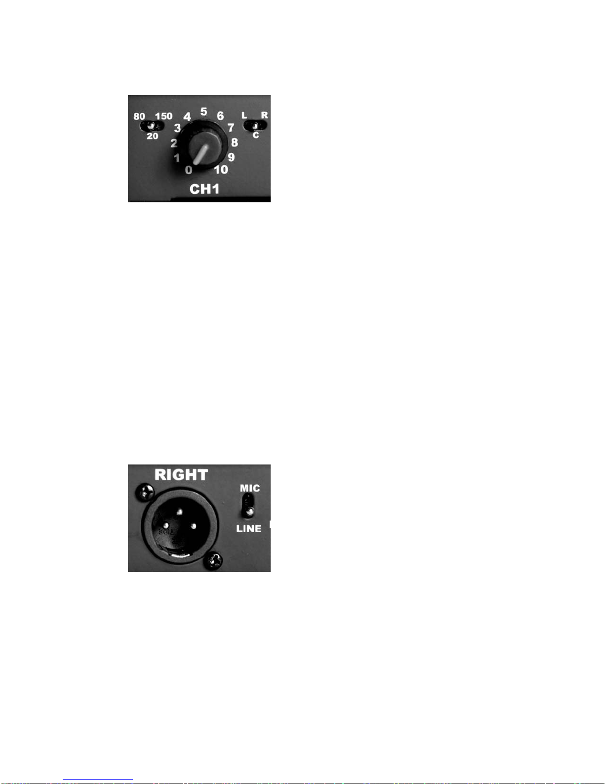
Low Cut Filters (80Hz, 20Hz, 150Hz)
Pan Switches (Left, Center, Right)
Channel Faders (Volume Controls)
Meters (-20 to +3dBv, Green, Amber, Red)
Headphone Monitor (Direct, Tape return)
Headphone Volume (Min to Max)
Power Switch (Internal Battery, Off, External Power)
Input Level Switch: Line Level (0dB Gain), Dynamic Mic (60dB Gain),
Condenser Mic (45dB Gain)
48PH Switch (Applies 48V Phantom Power for 48PH Mics)
Input XLR Female Connector
Output XLR Male Connector
Output Level Switch: Line Level (0dBv nominal balanced signal)
Microphone Level (-50dBv nominal balanced signal)
3.5MM Headphone Jack
3.5MM Tape Return Jack

6
3.5MM Microphone Level Output Jack (-50dBv nominal level)
Left and Right Tape Return Level Adjustments
Battery Compartment (2x 9V Alkaline)
External Power Input (7 to 16Vdc)
INPUTS:
A. BALANCED INPUTS
The PSC DV Promix 3 Audio Mixer provides three input channels utilizing female
XLR connectors. The studio grade input circuitry is electronically balanced for
improved RF rejection and in-field practicality. The XLR connectors are wired as
follows: Pin 1 shield (ground), Pin 2 Audio high (in phase), Pin 3 Audio low (out of
phase). Balanced wiring enables longer cable runs without the worry of
excessive noise due to nearby electromagnetic and radio frequency interference.
These balanced inputs may be unbalanced if desired. Either pin 2 or 3 may be
tied to ground (pin 1) to unbalance the inputs of the DV Promix 3.

7
B. INPUT LEVELS
The PSC DV Promix 3 Mixer can accommodate a wide range of input levels.
Microphone levels of all types can be handled as well as line level signals. The
input range of the DV Promix 3 Mixer is –60dBu to +4dBu. Thus the DV Promix
3 is compatible with all forms of consumer and professional audio equipment.
The input level switches are located to the left of each input XLR connector.
These input level switches provide for three level settings: “D” Dynamic
Microphone (60dB gain), “C” Condenser Microphone (45dB gain), and “L” Line
Level (0dB gain) These input level gain settings are used to correctly interface
sources of varying levels to the DV Promix 3’s preamplifiers. Correct level
matching ensures maximum headroom and the lowest possible noise floor. For
most circumstances, you should use the “Dynamic” setting for use with Dynamic
(non-powered) microphones such as the Shure SM-58 or Electro-Voice RE50.
You should use the “Condenser” setting when you use microphones such as the
Sennheiser ME-80/K6, Audio Technica AT-897 and other powered shot gun style
microphones. You should use the Line Level setting when connecting line level
sources to the DV ProMix 3 such as CD Players, MP3 Players and wireless
receivers with line level outputs. Keep in mind that dynamic microphones have a
low inherent output level that requires that the pre-amp provide maximum gain,
condenser microphone have a higher output level and thus require somewhat
less pre-amplifier gain and line level sources do not require any gain from the
pre-amplifier.
PLEASE SEE THE INPUT SETTING CHART AT THE END OF THIS MANUAL
FOR FURTHER RECOMMENDATIONS.

8
C. MICROPHONE POWERING
The DV Promix 3 Mixer can accommodate the most popular microphones used
today. The microphone powering switches are located directly left of the input
XLR connectors. They can be switched to either Dynamic (D) or 48Phantom
(48PH).
In the Dynamic position the mixer provides no microphone powering. This
position is used with Dynamic Microphones, Line Level inputs and when using
Wireless Receivers.
In the 48 Phantom Position the mixer provides 48 volts DC to power 48PH
microphones or simplex powered microphones with a range of 9 to 52 volts. Pin
1 is ground while pins 2 and 3 carry 48 volts DC. The term “phantom” is derived
from the fact that there is no voltage potential developed across a dynamic
microphone transducer that would interfere with its operation. However, most
portable wireless receivers will not operate properly with 48PH turned on. We
strongly recommend setting inputs to dynamic for use with all wireless systems.
**NOTE** Only use the 48PH microphone power when using microphones
that are designed to operate from 48PH. When in doubt, check the
operational instructions that came with your microphone.
PLEASE SEE THE INPUT SETTING CHART AT THE END OF THIS MANUAL
FOR FURTHER SUGGESTIONS.

9
D. LOW CUT FILTERS
Low cut filtering is important in location recording where wind noise can cause
pre-amplifier overload. This effect can be minimized by switching the low cut
filter setting to either 80Hz or 150Hz. Each input channel of the DV Promix 3
Mixer is equipped with a low cut filter. These filters are activated via the three
way switches located to the left of the adjacent channel fader knobs. These
filters will attenuate all frequencies below a preset frequency at a rate of 6dB per
octave. When set at “20Hz”, frequencies below 20 Hz are effectively rolled off
with the mixer operating at full frequency response. Optional low cut filter
settings of 80Hz and 150Hz will roll off the frequencies below these figures at a
rate of 6dB per octave (-3dB level at 80Hz and 150Hz respectively). Always use
the minimum filter setting required for the job. For example, if you are indoors or
outdoors on a windless day, use the 20Hz setting. For outdoor use with low wind
conditions, use the 80Hz setting. For recording in high winds, use the 150Hz
setting.
E. CHANNEL GAIN
In order to limit noise and increase headroom, the channel fader controls are
located in the feedback path of the pre-amplifiers. This provides continuously
variable gain rather than just a decrease in channel output level when an
overload situation occurs. This results in increased headroom and lower chance
of signal clipping (severe distortion).
10
F. CHANNEL PANS (CHANNEL ASSIGNMENT SWITCHES)
The new DV Promix 3 Audio Mixer contains front panel mounted pan switches.
These pan switches are used to route the individual input channel’s signal to
either the left or right summing buss and subsequent left and right outputs.
When set to the left position, audio from that particular input is routed to the left
output only. When set to the center position, audio from that particular input is
routed to both left and right outputs. When set to the right position, audio form
that particular input is routed to the right output only. These functions are easily
viewed when watching the meters. If you have a particular input set “panned” to
the left only, you will see the audio register on the left output meter only. The
same holds true for inputs panned to the right. In that case, you will only see
activity on the right meter.
OUTPUTS:
A. BALANCED OUTPUTS (XLR Connectors)
The DV Promix 3 Mixer contains very high quality electronically balanced
outputs. This circuitry has been designed to provide wide bandwidth, low
distortion and real-world ease of use. These outputs are available via the right
hand panel mounted male XLR connectors. These outputs are switchable
between line or microphone levels. At the line level setting, the mixer outputs
deliver a nominal 0dBv signal into 10K Ohm loads. When set to microphone
level, the outputs supply a nominal –50dBv signal levels ensuring compatibility
Inhaltsverzeichnis


