Ebyte ME31-XAAX0440 Bedienungsanleitung

Chengdu Ebyte Electronic Technology Co.,Ltd. ME31-XAAX0440_UserManul_EN
Copyright ©2012–2021,Chengdu Ebyte Electronic Technology Co.,Ltd. 0
ME31-XAAX0440
Network I/O networking module

Chengdu Ebyte Electronic Technology Co.,Ltd. ME31-XAAX0440_UserManul_EN
Copyright ©2012–2021,Chengdu Ebyte Electronic Technology Co.,Ltd. 1
Contents
Chapter 1 Introduction...........................................................................................................................................................1
1.1 Brief Introduction..................................................................................................................................................... 1
1.2 Features.....................................................................................................................................................................1
1.3 Product application topology diagram......................................................................................................................2
Chapter 2 Quick start.............................................................................................................................................................. 3
2.1 Preparation for use....................................................................................................................................................3
2.2 Device connection.................................................................................................................................................... 4
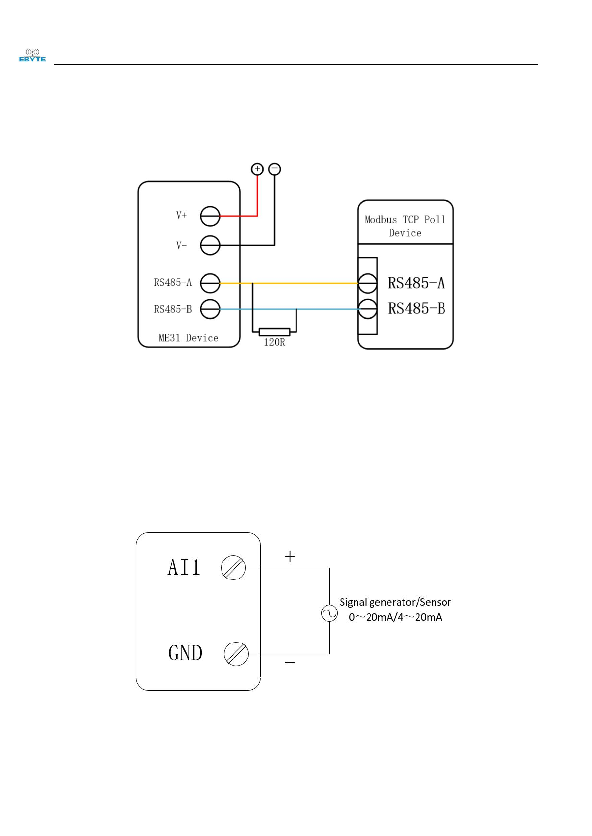
2.2.1 RS485 connection..........................................................................................................................................4
2.2.2 Analog input connection................................................................................................................................ 4
2.2.3 Relay output connection................................................................................................................................ 5
2.2.4 Simple to use..................................................................................................................................................5
2.3 Parameter configuration............................................................................................................................................5
2.4 Control test................................................................................................................................................................7
2.4.1 Modbus TCP control......................................................................................................................................7
2.4.2 Modbus RTU control..................................................................................................................................... 8
2.5 Host computer control.............................................................................................................................................. 8
Chapter 3 Technical index...................................................................................................................................................... 9
3.1 Specifications............................................................................................................................................................9
3.2 Device default parameters...................................................................................................................................... 10
3.3 Mechanical dimension drawing.............................................................................................................................. 10
3.4 Port description....................................................................................................................................................... 11
3.5 LED indicator description.......................................................................................................................................12
Chapter 4 Product function introduction.............................................................................................................................. 13
4.1 DO output mode..................................................................................................................................................... 13
4.1.1 Level output................................................................................................................................................. 13
4.1.2 Pulse output................................................................................................................................................. 13
4.1.3 Power-on state..............................................................................................................................................13
4.2 AI input mode......................................................................................................................................................... 13
4.2.1 Analog range................................................................................................................................................ 13
4.2.2 AI raw value and engineering value of analog input................................................................................... 14
4.2.3 Input filter parameters..................................................................................................................................14
4.2.4 Input calibration...........................................................................................................................................14
4.3 Modbus gateway.....................................................................................................................................................14
4.4 Active upload.......................................................................................................................................................... 15
4.5 Custom module information................................................................................................................................... 15
4.5.1 Modbus address........................................................................................................................................... 15
4.5.2 Module name............................................................................................................................................... 15
4.5.3 Network parameters.....................................................................................................................................15
4.5.4 Serial port parameters.................................................................................................................................. 16
4.6 LCD display and parameter configuration............................................................................................................. 16
4.6.1 Information display interface.......................................................................................................................16
4.6.2 Device parameter display interface..............................................................................................................17

Chengdu Ebyte Electronic Technology Co.,Ltd. ME31-XAAX0440_UserManul_EN
Copyright ©2012–2021,Chengdu Ebyte Electronic Technology Co.,Ltd. 2
4.6.3 Parameter configuration...............................................................................................................................17
4.7 Modbus TCP protocol data frame description........................................................................................................ 18
4.8 Modbus RTU protocol data frame description....................................................................................................... 18
4.9 MODBUS parameter configuration........................................................................................................................19
4.9.1 DO related registers..................................................................................................................................... 19
4.9.2 AI register list.............................................................................................................................................. 19
4.9.3 Module related registers.............................................................................................................................. 20
4.9.4 Network related registers............................................................................................................................. 21
4.9.5 Modbus instruction operation instructions.................................................................................................. 22
Chapter 5 Host computer...................................................................................................................................................... 24
5.1 Acquisition and control...........................................................................................................................................24
5.2 Parameter configuration..........................................................................................................................................25
Chapter 6 About customization............................................................................................................................................ 27
Revision history.................................................................................................................................................................... 28
About us................................................................................................................................................................................28

Chengdu Ebyte Electronic Technology Co.,Ltd. ME31-XAAX0440_UserManul_EN
Copyright ©2012–2021,Chengdu Ebyte Electronic Technology Co.,Ltd. 1
Chapter 1 Introduction
1.1 Brief Introduction
ME31-XAAX0440 has 4 Type A relay outputs and 4 analog (0-20mA/4-20mA) inputs,
supports Modbus TCP protocol or Modbus RTU protocol for acquisition and control, and
the device can also be used as a simple Modbus gateway (Automatically send commands
of non-local Modbus addresses through the serial port/network port) network I/O
networking module.
1.2 Features
Support standard Modbus RTU protocol and Modbus TCP protocol;
Support various configuration software/PLC/touch screen;
RS485 acquisition and control I/O;
RJ45 acquisition and control I/O;
4 analog inputs (0-20mA/4-20mA);
4-way switch output DO (type A relay);
Switch output (DO) supports level mode and pulse mode;
Support custom Modbus address setting;
Support 8 common baud rate configurations;
Support DHCP and static IP;
Support DNS function, domain name resolution;

Chengdu Ebyte Electronic Technology Co.,Ltd. ME31-XAAX0440_UserManul_EN
Copyright ©2012–2021,Chengdu Ebyte Electronic Technology Co.,Ltd. 2
1.3 Product application topology diagram
Modbus TCP application request topology:
Modbus RTU application request topology:

Chengdu Ebyte Electronic Technology Co.,Ltd. ME31-XAAX0440_UserManul_EN
Copyright ©2012–2021,Chengdu Ebyte Electronic Technology Co.,Ltd. 3
Chapter 2 Quick start
[Note] This experiment needs to be performed by default factory parameters.
2.1 Preparation for use
The following table is the required materials for this test:
ME31-XAAX0440
12V Switching power supply
USB to RS485
Computer
One network cable
Several cables4
Chengdu Ebyte Electronic Technology Co.,Ltd. ME31-XAAX0440_UserManul_EN
Copyright ©2012–2021,Chengdu Ebyte Electronic Technology Co.,Ltd. 4
2.2 Device connection
2.2.1 RS485 connection
[Note] When the RS485 bus high-frequency signal is transmitted, the signal wavelength is shorter than the transmission
line, and the signal will form a reflection wave at the end of the transmission line, which will interfere with the original
signal. Therefore, a terminal resistance must be added at the end of the transmission line to prevent the signal from
reflecting after reaching the end of the transmission line. The terminal resistance should be the same as the impedance of
the communication cable, with a typical value of 120 ohms. Its function is to match the bus impedance and improve the
anti-interference and reliability of data communication.
2.2.2 Analog input connection

Chengdu Ebyte Electronic Technology Co.,Ltd. ME31-XAAX0440_UserManul_EN
Copyright ©2012–2021,Chengdu Ebyte Electronic Technology Co.,Ltd. 5
2.2.3 Relay output connection
2.2.4 Simple to use
Wiring: The computer is connected to the RS485 interface of ME31-XAAX0440 through USB to RS485, A is
connected to A, B is connected to B.
Networking: Insert the network cable into the RJ45 port and connect to the PC.
Power supply: Use DC-12V switching power supply (DC 8~28V) to supply power to ME31-XAAX0440.
2.3 Parameter configuration
Step 1: Modify the IP address of the computer to be consistent with the device, here I am modified to 192.168.3.100 to
ensure that it is in the same network segment as the device and that the IP is different;

Chengdu Ebyte Electronic Technology Co.,Ltd. ME31-XAAX0440_UserManul_EN
Copyright ©2012–2021,Chengdu Ebyte Electronic Technology Co.,Ltd. 6
Step 2: Open the network assistant, select the TCP client, enter the remote host IP192.168.3.7 (default parameter), enter
the port number 502 (default parameter), and select HEX to send.

Chengdu Ebyte Electronic Technology Co.,Ltd. ME31-XAAX0440_UserManul_EN
Copyright ©2012–2021,Chengdu Ebyte Electronic Technology Co.,Ltd. 7
2.4 Control test
2.4.1 Modbus TCP control
Use the network assistant to control the first DO output of ME31-XAAX0440.
You can test other functions through the commands in the following table.
Function (function code)
Instruction
Pull in the first coil (0x05)
01 00 00 00 00 06 01 05 00 00 FF 00
Full open command (0x0F)
02 00 00 00 00 08 01 0F 00 00 00 04 01 0F
Full close instruction (0x0F)
02 00 00 00 00 08 01 0F 00 00 00 04 01 00
Read all AI inputs (0x04)
01 00 00 00 00 06 01 04 00 64 00 04
Read all DO status (0x01)
01 00 00 00 00 06 01 01 00 00 00 04
The input register read by the demo case is engineering quantity (16-bit integer value, 32-bit floating point value
can also be obtained by reading 0x00C8 register)
Convert the value read from the input register to decimal, and compare it with the value displayed on the screen
after dividing by 1000.
Andere Handbücher für ME31-XAAX0440
1
Inhaltsverzeichnis
Andere Ebyte E/A-System Handbücher


Beliebte E/A-System Handbücher anderer Marken

WAGO
WAGO 750-344 Bedienungsanleitung

Teknim
Teknim TWM-1887 Bedienungsanleitung

Intelligent Appliance
Intelligent Appliance IA-2662-E Bedienungsanleitung

BERGHOF
BERGHOF ECC DIO 16/16 Bedienungsanleitung

Advantech
Advantech PCM-27J3AU Installations- und Betriebshandbuch

Festo
Festo CP-E08-M12-CL Bedienungsanleitung


