EG4 8KEXP-240V Bedienungsanleitung

EG4 Electronics www.eg4electronics.com
USER MANUAL
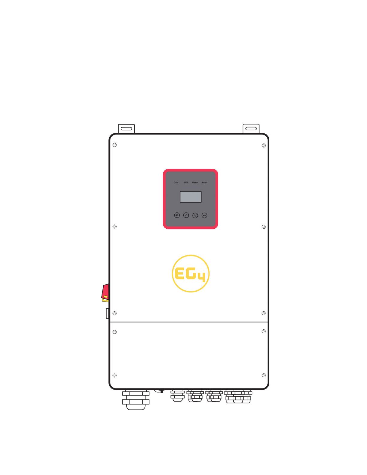
EG4 8KEXP-240V
HYBRID INVERTER/CHARGER
8000W 120/240 VAC
9HUVLRQ11RYHPEHU

Table of Contents
1. NOTES ON THIS MANUAL…………………………………………………………..3
1.1 SCOPE OF VALIDITY………………………………………………………………………………………………..3
1.2 TARGET GROUP ……………………………………………………………………………………………………..3
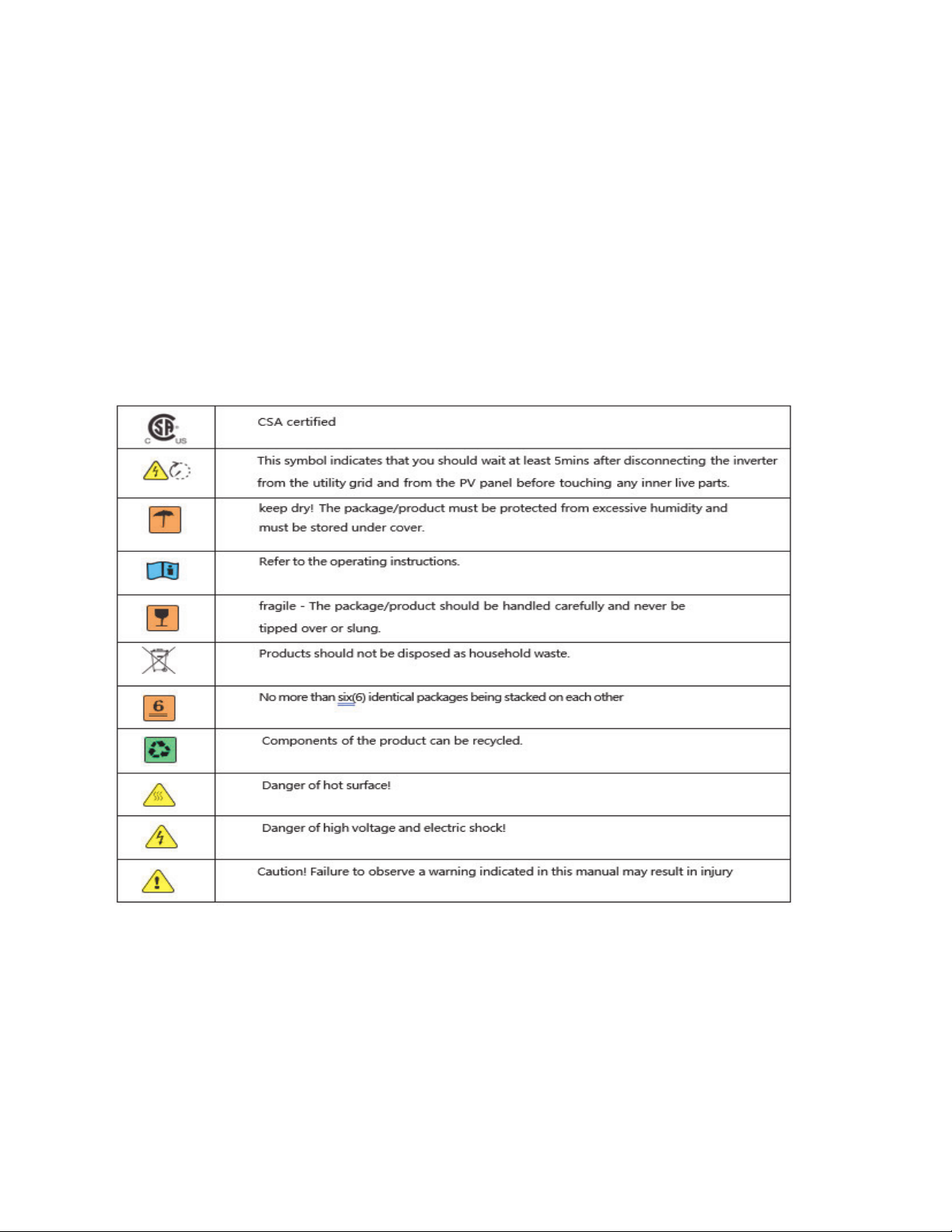
1.3 SYMBOLS USED………………………………………………………………………………………………………3
2. SAFETY...………………………………………………………………………………..4
2.1 IMPORTANT SAFETY INSTRUCTIONS………………………………………………………………………..4
2.2 EXPLANATION OF SYMBOL………………………………………………………………………………………7
3. INTRODUCTION...…………………………………………………………………....7
3.1 BASIC FEATURES…………………………………………………………………………………………………...7
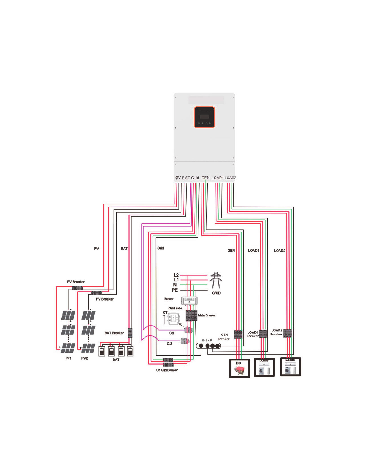
3.2 SYSTEM DIAGRAM………………………………………………………………………………………………….8
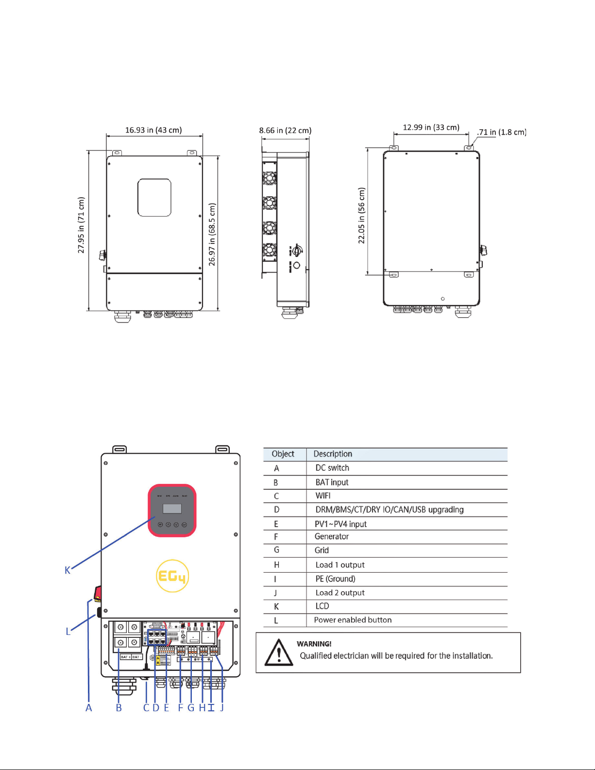
3.3 DIMENSION…………………………………………………………………………………………………………..9
3.4 TERMINALS OF PV INVERTER………………………………………………………………………………….9
4. TECHNICAL PARAMETERS..……………………………………………………...10
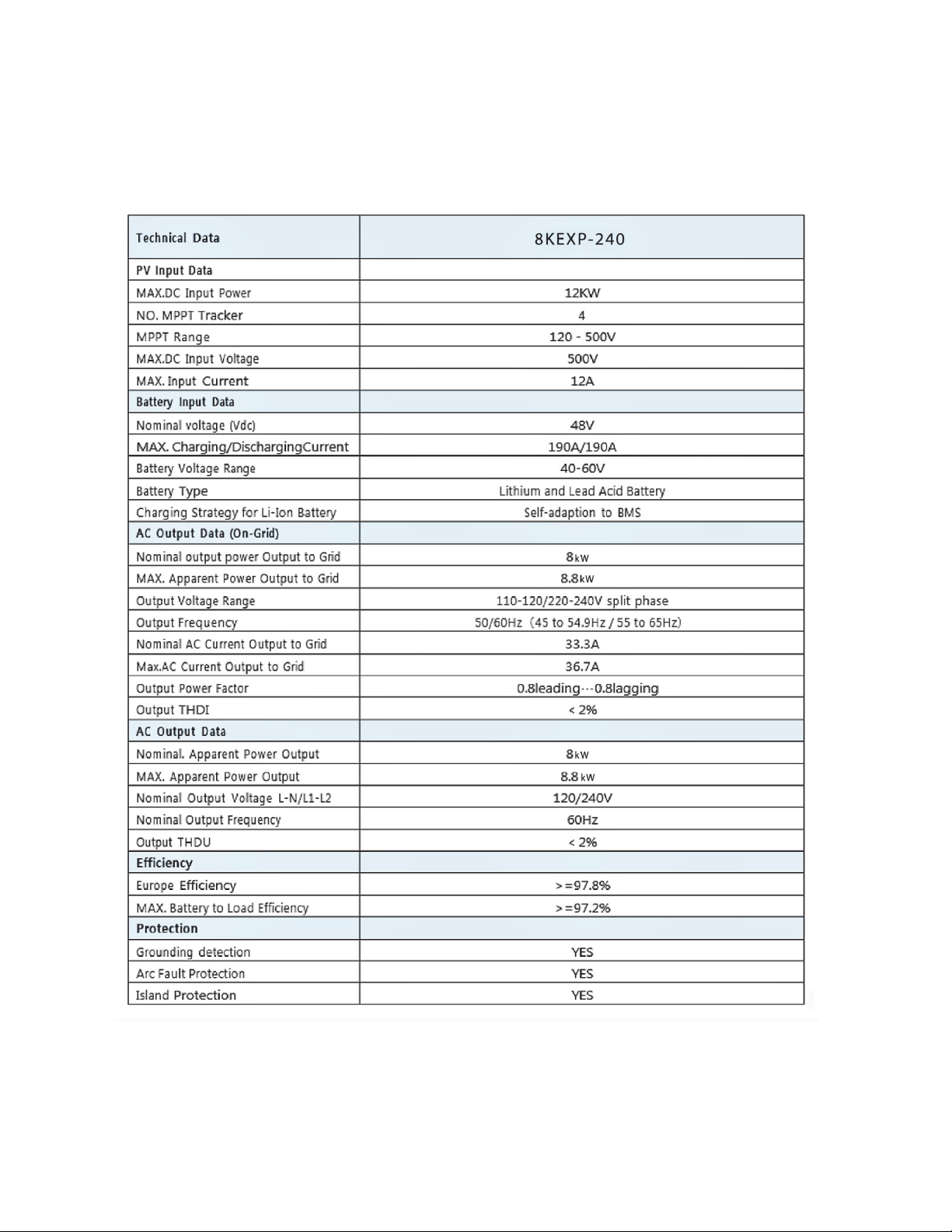
4.1 INVERTER SPECIFICATION…………………………………………………………………………………….10
5. INSTALLATION………………………………………………………………………12
5.1 CHECK FOR PHYSICAL DAMAGE……………………………………………………………………………..12
5.2 PACKING LIST……………………………………………………………………………………………………….12
5.3 MOUNTING…………………………………………………………………………………………………………..12
6. ELECTRICAL CONNECTION……………………………………………………….15
6.1 PV CONNECTION…………………………………………………………………………………………………..15
6.2 GRID CONNECTION (GEN CONNECTION)...................................................................16
6.3 LOAD1 AND LOAD2 CONNECTION………………………………………………………………………….17
6.4 BATTERY CONNECTION…………………………………………………………………………………………19
6.5 WIFI CONNECTION (OPTIONAL)...............................................................................2
6.6 CT INSTALLATION INSTRUCTIONS………………………………………………………………………...2
7. LCD OPERATION…………………………………………………………………….2
7.1 CONTROL PANEL…………………………………………………………………………………………………..2
7.2 INSTRUCTIONS FOR LED INDICATOR……………………………………………………………………..2
7.3 OUTLINE FOR SETTINGS MENU……………………….…………………………………………………….2
8. LCD OPERATION…………………………………………………………………….2
8.1 LCD OPERATION……………………………………………………………………………………………………2
8.2 SETTING………………………………………………………………………………………………………………2
9. FAULT DIAGNOSIS AND SOLUTIONS..………………………………………..4
10.INVERTER PARALLEL GUIDE……………………………………………………4
10.1 PARALLEL SYSTEM DIAGRAM…………………………………………………………………………………4
10.2 PARALLEL COMMUNICATION CABLE CONNECTION………………………………………………….4
10.3 PARALLEL OPERATION NOTES……………………………………………………………………………….4
10.4 PARALLEL SYSTEM SETTINGS………………………………………………………………………………..4
6.4 (*B06 C20081,&$7,216(783…………………………………………………………………………
11. STICK LOGGER GUIDE...........................................................................48

1 Notes on this Manual
1.1 Scope of Validity
This manual describes installation, commissioning, operation, and troubleshooting. Please read
the manual fully and carefully before installing and operating. This manual provides basic safety and
installation guidelines as well as information on tools and wiring. Keep this manual for future use.
1.2 Target Group
This manual is for qualified electricians and owner/builders with qualified electrician
oversight.
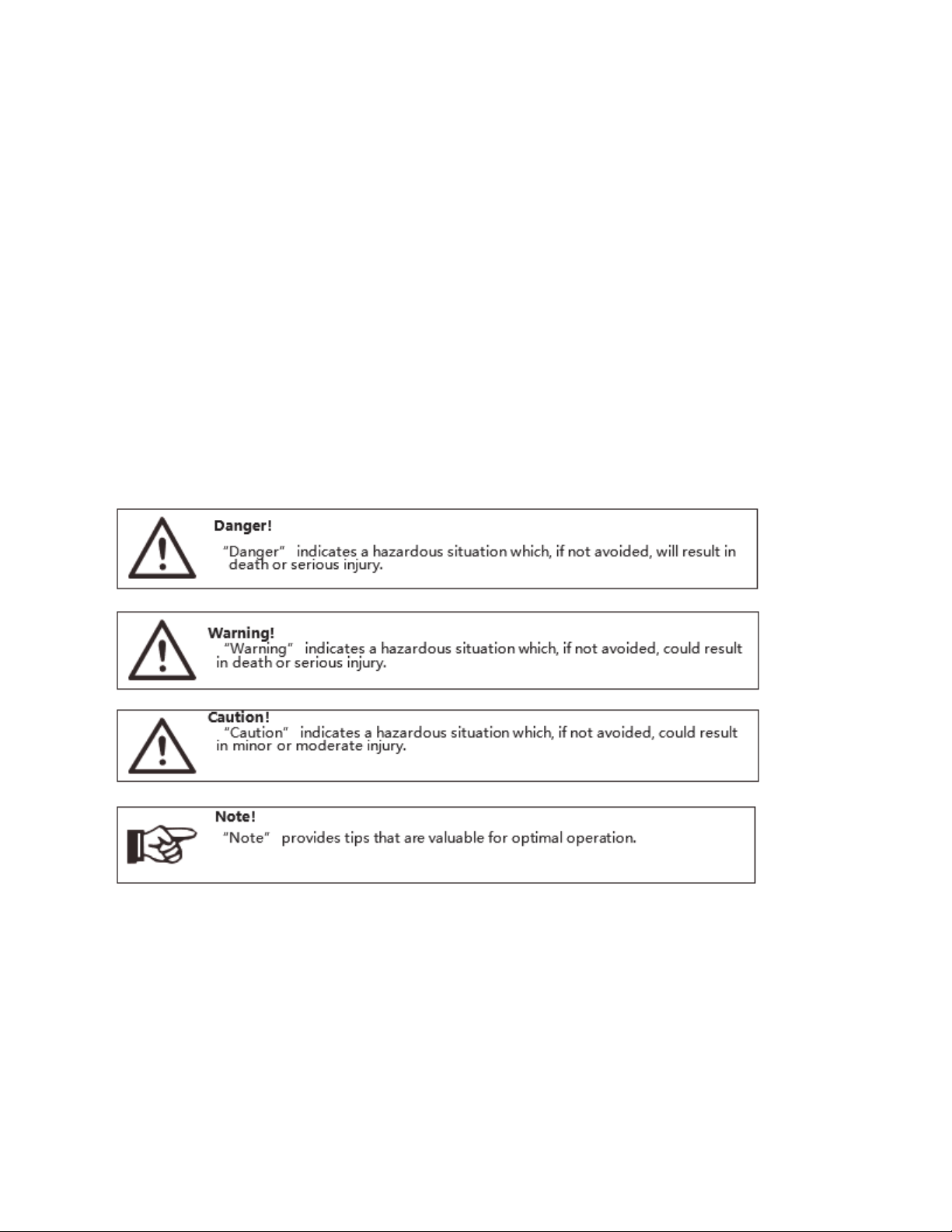
1.3 Symbols Used
The following types of safety instructions and general information appear in this document as
described below:

2Safety
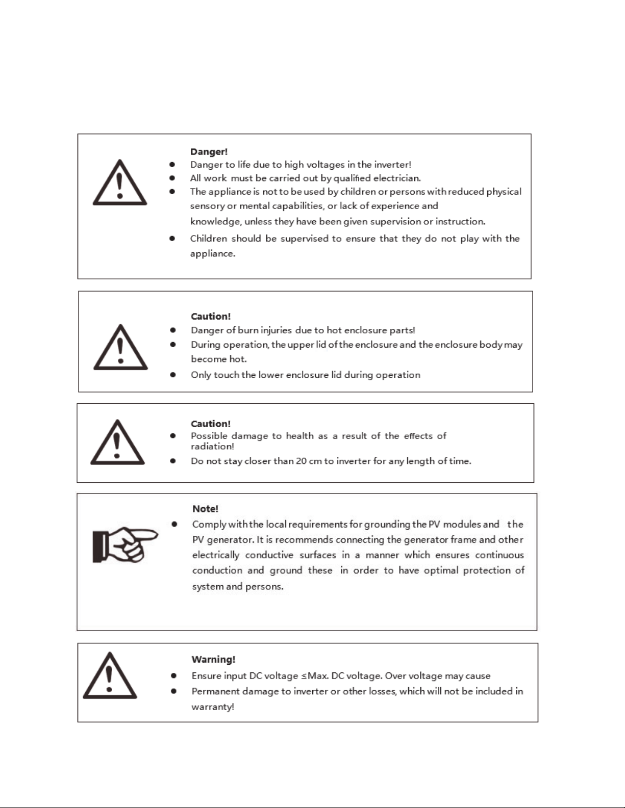
2.1 Important Safety Instructions

ƔPlease keep this user manual for future use. Always follow the precautions, and safety
instructions in this document. EG4 will not be liable for any consequence caused by the violation
of the safety regulations, design, production, and usage standards.
ƔOnly accessories included with the inverter shipment are recommended for use with the inverter.
Modification or unapproved components may result in a risk of fire, electric shock, or injury to
person.
ƔMake sure that existing wiring is in good condition and that wire is not undersized. Do not
disassemble any parts of the inverter which are not mentioned in the installation guide. It
contains no user-serviceable parts. See Warranty for instructions on obtaining service. Attempting
to service the inverter yourself may result in a risk of electric shock or fire and will void your
warranty.
ƔKeep away from flammable, explosive materials to avoid possible fires.
ƔThe installation place should be away from humid or corrosive substances.
ƔAuthorized service personnel must use insulated tools when installing or working with this
equipment.
ƔNever touch either the positive or negative pole of a PV connecting device. Never touch both of
them at the same time.
ƔThe unit contains capacitors that remain charged to a potentially lethal voltage after the
utility, battery and PV supply has been disconnected.
ƔHazardous voltage will present for up to 5 minutes after disconnection from the power supply.
ƔCAUTION-RISK of electric shock from energy stored in capacitor, never perform maintenance on
the inverter couplers, utility cables, battery cables, or PV cables while power is applied. After
switching off the PV, battery and utility; wait for 5 minutes to let the intermediate circuit
capacitors discharge before unplugging PV, battery, and utility couplers.
ƔWhen accessing the internal circuit of the inverter, it is very important to wait 5 minutes before
operating the power circuit or demounting the electrolyte capacitors inside the device. Do not
open the device beforehand since the capacitors require time sufficiently discharge!
ƔPlease use surge protection devices (SPDs) for PV installation.

ƔLightning will cause damage either from a direct strike or from surges due to a nearby strike.
ƔInduced surges are the most likely cause of lightning damage in majority or installations,
especially in rural areas where electricity is usually provided by long overhead lines. Surge may
be included on both the PV array conduction and the AC cables leading to the building.
ƔSpecialists in lightning protection should be consulted during the end use application. Using
appropriate external lightning protection, the effect of a direct lightning strike into a building can
be mitigated in a controlled way.
ƔInstallation of SPDs to protect the inverter against mechanical damage and excessive stress
include a surge arrester in case of a building with external lightning protection system (LPS)
when separation distance is kept.
ƔTo protect the DC system, a surge suppression device (SPD type2) should be fitted at the inverter
end of the DC cabling and at the array located between the inverter and the PV generator. If the
voltage protection level (VP) of the surge arresters is greater than 1100V, an additional SPD type
3 is required for surge protection for electrical devices.
ƔTo protect the AC system, surge suppression devices (SPD type2) should be fitted at the main
incoming point of AC supply (at the consumers cutout), located between the inverter and the
meter/distribution system.
ƔAll DC cables should be installed to provide as short a run as possible, and positive and negative
cables of the string or main DC supply should be bundled together. This avoids the creation of
loops in the system.
ƔSpark gap devices are not suitable to be used in DC circuits once conducting, they won’t stop
conducting until the voltage across their terminals is typically more than 30 volts.
䚔Anti-Islanding Effect
Islanding effect is a special phenomenon that grid-connected PV system still supply power to the nearby
grid when the voltage loss is happened in the power system. It is dangerous for maintenance personnel
and the public. This inverter provides Active Frequency Drift(AFD) to prevent islanding effect.
䚔PE Connection and Leakage Current
The end-use application shall monitor the protective conductor by residual current operated protective
device (RCD) with rated fault current Ifn≤240mA. This automatically disconnects the device in case of a
fault. The device is intended to connect to a PV generator with a capacitance limit of approximately
700nf.
Incorrect grounding can cause physical injury, death or equipment malfunction.

䚔Battery Safety Instructions
This inverter must use low voltage batteries. For the specific parameters such as battery type, nominal
voltage and nominal capacity etc., please refer to section 4.3.
Connecting batteries in parallel contains risk of potential electric shock and short-circuit current danger.
To avoid accidents, the following warnings should be observed during battery replacement:
1: Do not wear watches, rings or similar metallic items.
2: Use insulated tools.
3: Put on rubber shoes and gloves.
4: Do not place metallic tools and similar metallic parts on the batteries.
5: Switch offload connected to the batteries before dismantling battery connection terminals.
6: Only personnel with proper expertise can carry out the maintenance of batteries.
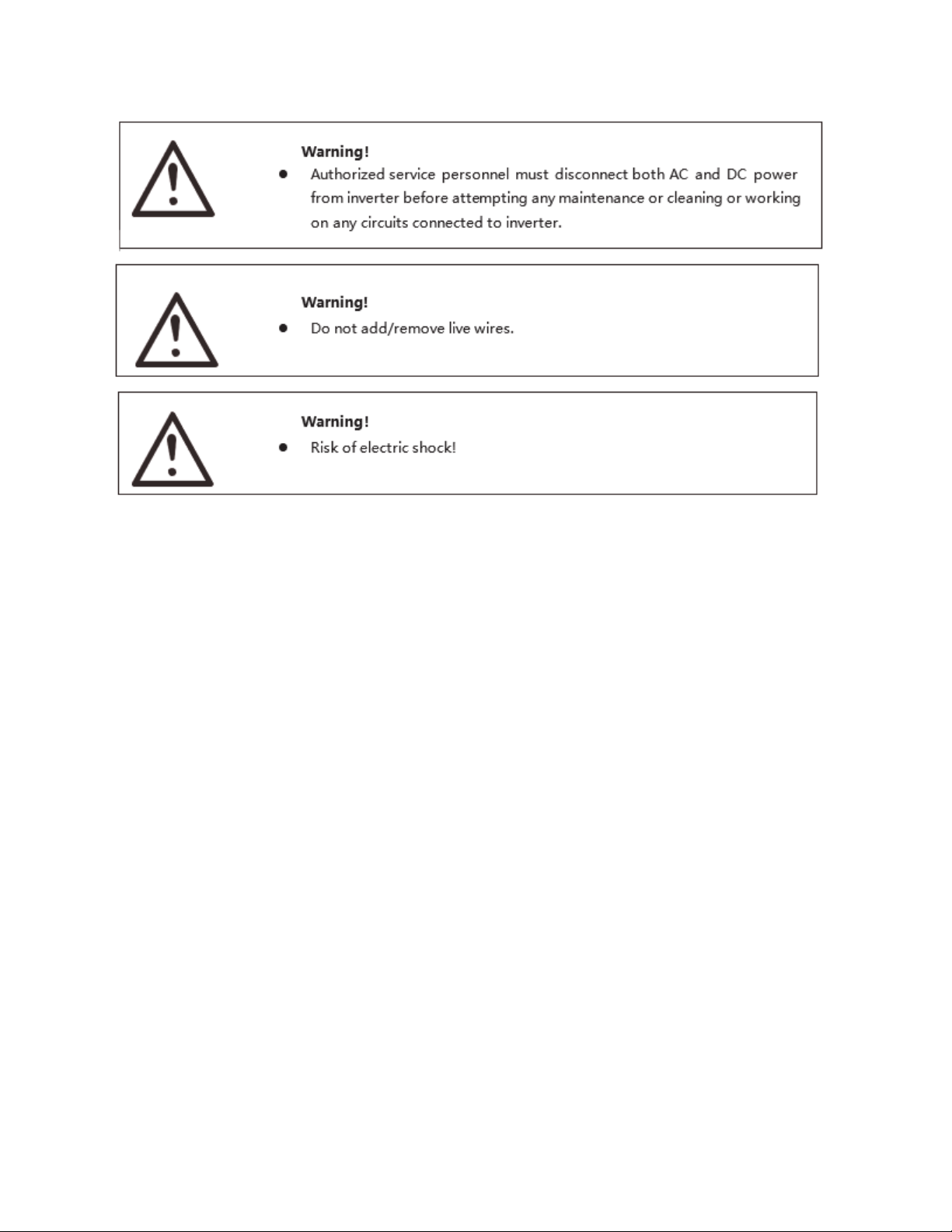
2.2 Explanation of Symbols
3. Introduction
3.1 Basic features
The EG4 8KEXP-240 is a high-quality hybrid inverter which can convert solar energy to AC energy and
store the energy in batteries. This inverter can be used to optimize self-consumption, store in the battery
for future use or feed into the public grid. Work mode depends on PV energy and the user's preference. It
can provide power for emergency use during grid loss by using the energy from the battery and inverter
(generated from PV).

3.2 System Diagram

3.3 Dimension
3.4 Terminals of PV inverter

4. Technical Parameters
4.1 Inverter specification
Inhaltsverzeichnis
Andere EG4 Wechselrichter Handbücher

EG4
EG4 3000 EHV-48 Bedienungsanleitung
EG4
EG4 6500 EX-48 Bedienungsanleitung

EG4
EG4 18KPV Bedienungsanleitung

EG4
EG4 6500 Bedienungsanleitung

EG4
EG4 6000EX-48 Bedienungsanleitung

EG4
EG4 6000EX-48HV Bedienungsanleitung

EG4
EG4 6500 EX-48 Bedienungsanleitung

EG4
EG4 3000 EHV-48 Bedienungsanleitung

EG4
EG4 6000XP Bedienungsanleitung

EG4
EG4 6000XP Bedienungsanleitung