
Environmental Technologies FWT-3H Bedienungsanleitung

4fo1egaP2 rev A May 2008
9091#ITE
We Manage Heat®
FWT®- 3H Hydronic Thermostat
(Order Number 19090)
Installation And Operating Instructions
Environmental Technology, Inc.
1850 N Sheridan Street
South Bend, Indiana 46628
(800) 234-4239
FAX (888) 234-4238

4fo2egaP2 rev A9091#ITE
DISCLAIMER
Environmental Technology, Inc makes no representations or warranties, either expressed or implied, with respect to the contents of this
publication or the products that it describes, and specifically disclaims any implied warranties of merchantability or fitnessfor any particular
purpose. Environmental Technology, Inc. reserves the right to revise this publication and to make changes and improvements to the
products described in this publication without the obligation of Environmental Technology, Inc. to notify any person or organization of
such revisions, changes or improvements.
Before disposing of the packing material, verify the inclusion of items in the packing list. Immediately notify CUSTOMER
SERVICE of any discrepancy or shipping damage.
Packing List
Quantity Part Number Description
1 19092 Installation and Operation Instructions
1 19088 FWT-3H Electronic Assembly
2 18581 Wall Plate Screw, White
1 19272 Temperature Sensor/Extension Cable
Installation
Mounting
The FWT-3H Electronic Assembly mounts in a single-gang switch box (customer supplied). Choose a mounting location that
is convenient and reasonably close to the temperature sensor. The Temperature Sensor comes with 20 feet (6.1m) of jacketed extension
cable. The cable length can be shortened if the entire 20 feet is not needed for the chosen mounting location. Shortening the cable will
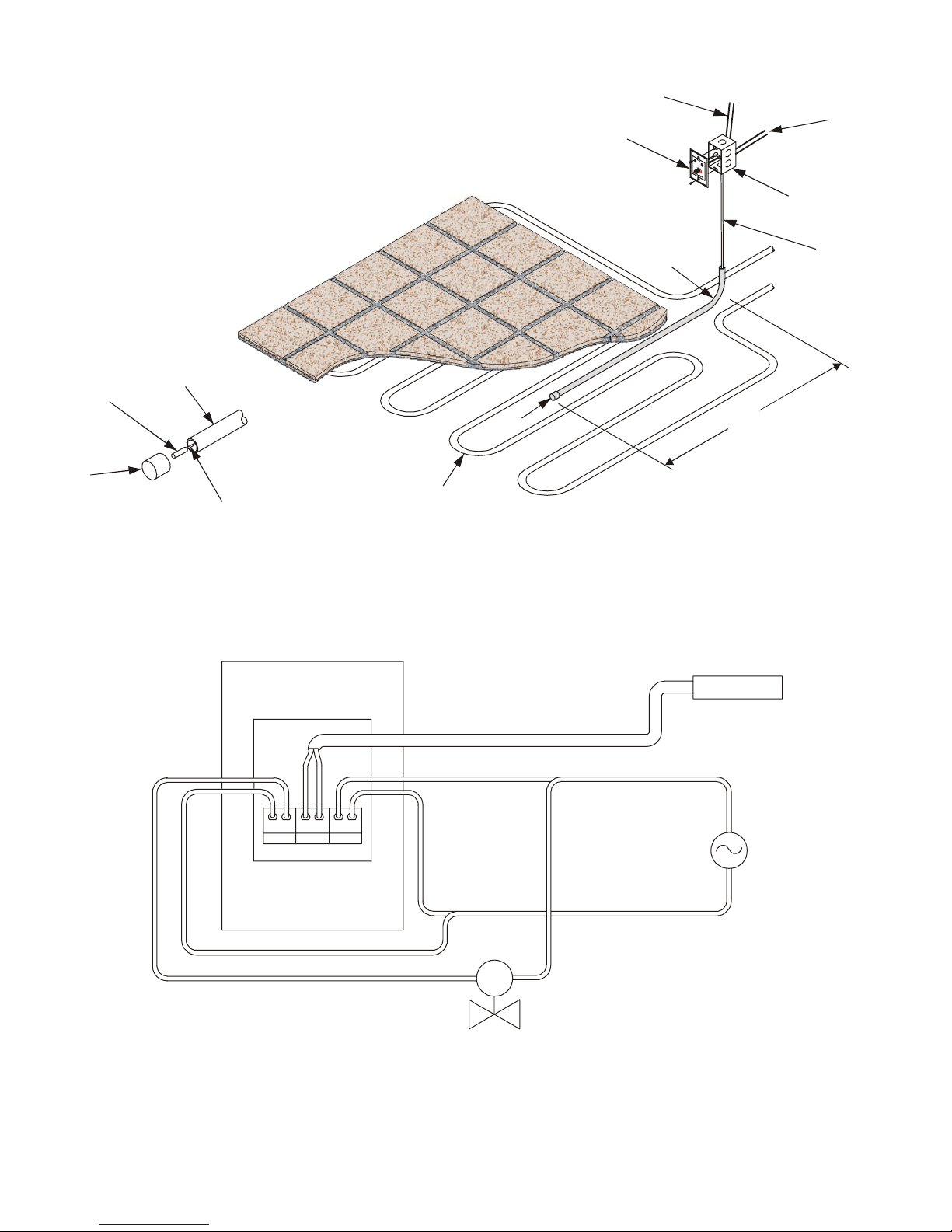
not affect performance of the FWT-3H. Locate the temperature sensor within the heated space as shown in Figure 1. Do not allow the
temperature sensor or extension cable to cross over or come in contact with any heating source such as a hydronic tubing run.
Though it is not required, it is highly recommended that the temperature sensor/extension cable be housed in conduit as shown.
This will make replacing the temperature sensor much easier in the unlikely event it ever needs to be replaced. The entire length of the
extension cable need not be housed in conduit; only the length traveling through the floor substrate and a short vertical section behind an
adjacent wall (generally where the extension cable rises up out of the floor substrate). Use thin wall conduit with a minimum diameter of
½". Be sure the temperature sensor can pass through the conduit unobstructed when the extension cable is fed through. Cap the end of
the conduit in the heated space prior to installation of the floor substrate. This avoids clogging the conduit and wedging the temperature
sensor against the conduit wall. Also make sure that the temperature sensor reaches the cap at the end of the conduit.
Wiring
Figure 2 shows the relay, Temperature Sensor and power source connections to the terminal block on the back of the FWT-3H
Electronic Assembly. A label on the terminal block identifies these connections. The relay is a normally open isolated contact rated at
3 Amps resistive, or 1 Amp inductive. The FWT-3H requires an NEC Class 2, 24 volt AC power source (customer supplied), rated at
5VA or higher to operate. Many hydronic systems use 24 volts AC, which is suitable for powering the FWT-3H. If power cannot be
derived from the hydronic system, a separate 24 volt AC Class 2 transformer must be used. If the controlled device (pump contactor, zone
valve, boiler control, etc.) is being supplied from the same power source supplying the FWT-3H, make sure the source has sufficient
VA capacity to supply both loads. When making the relay and power source connections, use #18 AWG stranded wires if the wire lengths
needed are less than 50 feet. For lengths more than 50 feet, but less than 150 feet, use #16 AWG stranded wires. For lengths greater than
150 feet, contact CUSTOMER SERVICE. Connect the temperature sensor extension cable leads into to the terminal block as shown in
Figure 2. Reversing these leads does not interfere with operation of the FWT-3H.
May 2008
4fo3egaP2 rev A May 2008
9091#ITE
FWT–3H
Single-Gang
Switch Box
(Customer Supplied)
3 ft. (approx.)
Cap
Hydronic Tubing Run
Extension Cable
Temperature
Sensor
Conduit for
temperature sensor /
extension cable
(Customer Supplied)
To 24VAC Class 2
Power supply
(Customer Supplied)
To controlled device
(contactor, zone valve, etc.)
Figure 1
FWT-3H Electronic Assembly/Temperature Sensor Mounting
Cap
Extension Cable
Conduit
FWT-3H Thermostat
(rear view)
Temperature Sensor
Jacketed Extension Cable
RELAY SENSOR 24 VAC
SV
Solenoid valve, pump contactor,
or boiler control
24 VAC
power source
Figure 2
FWT-3H Wiring Diagram

4fo4egaP2 rev A May 2008
9091#ITE
Operation
The green POWER indicator operates to show that power is available.
The yellow HEAT indicator operates and the relay contact closes during heating.
The knob sets the operating temperature. Clockwise rotation increases the temperature.
Full counterclockwise rotation puts the system or zone in IDLE mode which prevents heating. This feature saves energy by not heating
unoccupied areas. The HEAT indicator blinks slowly when the IDLE mode has been selected.
Troubleshooting
Our experience shows that installation errors cause the majority of problems. Frequently encountered problems include wiring errors.
Simple electrical tests and visual inspections usually identify these problems.
Neither indicator operates and there is no heat.
Power is probably not available - check the power source connection at the terminal block. If the problem persists with 24 volts
AC available and power wires are properly connected, the FWT-3H Electronic Assembly is probably defective. Contact
CUSTOMER SERVICE.
Both indicators operate continuously and there is no heat.
There may be an open circuit in the wiring between the RELAY connection and the controlled device (pump contactor, zone
valve, boiler control, etc.). If this wiring is ok and the problem persists, a malfunction in the controlled device or the hydronic
heating system is the likely source of the problem.
The yellow HEAT indicator blinks rapidly and there is no heat.
The FWT-3H is detecting an open circuit in the Temperature Sensor connection. When this happens, the relay remains de-
energized (contacts open), regardless of the temperature setting. Make sure the wires in the Temperature Sensor extension cable
are properly connected to the terminal block. If the wires are properly connected and the problem persists, the Temperature Sensor
extension cable has probably been severed at some location along its length. A defective Temperature Sensor is possible, though
unlikely.
There is continuous heat and the yellow HEAT indicator is off.
There may be a short circuit in the wiring between the RELAY connection and the controlled device. A short in this wiring can
emulate a continuously closed relay contact without illuminating the HEAT indicator. If the wiring is ok and the problem persists,
a malfunction in the controlled device or the hydronic heating system is the likely source of the problem.
QUESTIONS AND COMMENTS
For technical help, questions or comments concerning this product or any of Environmental Technology, Inc. products contact
the Customer Service Department between 8:00am and 5:00pm EST at:
Voice: 800.234.4239 (USA and Canada) Fax: 888.234.4238 (USA and Canada)
)erehwesle(2512.332.475)erehwesle(2021.332.475
E-mail: [email protected]
®
ENVIRONMENTAL TECHNOLOGY, INC.
1850 N Sheridan Street / South Bend, Indiana 46628 (574) 233-1202 / FAX (574) 233-2152 / Toll Free (800) 234-4239 / http://www.networketi.com
The ETI Logo, We Manage Heat and FWT are registered trademarks of Environmental Technology, Inc.
Copyright ©2008 Environmental Technology, Inc. All rights reserved.
Inhaltsverzeichnis
Andere Environmental Technologies Thermostat Handbücher


Beliebte Thermostat Handbücher anderer Marken

EWELLY
EWELLY EW-181 Bedienungsanleitung

Prolon
Prolon T1100 Montageanleitung

Computherm
Computherm Q20 Bedienungsanleitung

Heatmiser
Heatmiser neoStat Bedienungsanleitung

Aube Technologies
Aube Technologies TH111GFCI-NP 240 VCA Bedienungsanleitung

Mars
Mars HEAT CONTROLLER IR Wireless Thermostat Bedienungsanleitung


