Grünwalder Weg 28A . 82041 Oberhaching . Germany
phone: +49 (0 89 665180 0 . fax: +49 (0 89 665180 40 . www.fastcomtec.com
SPECIFICATIONS
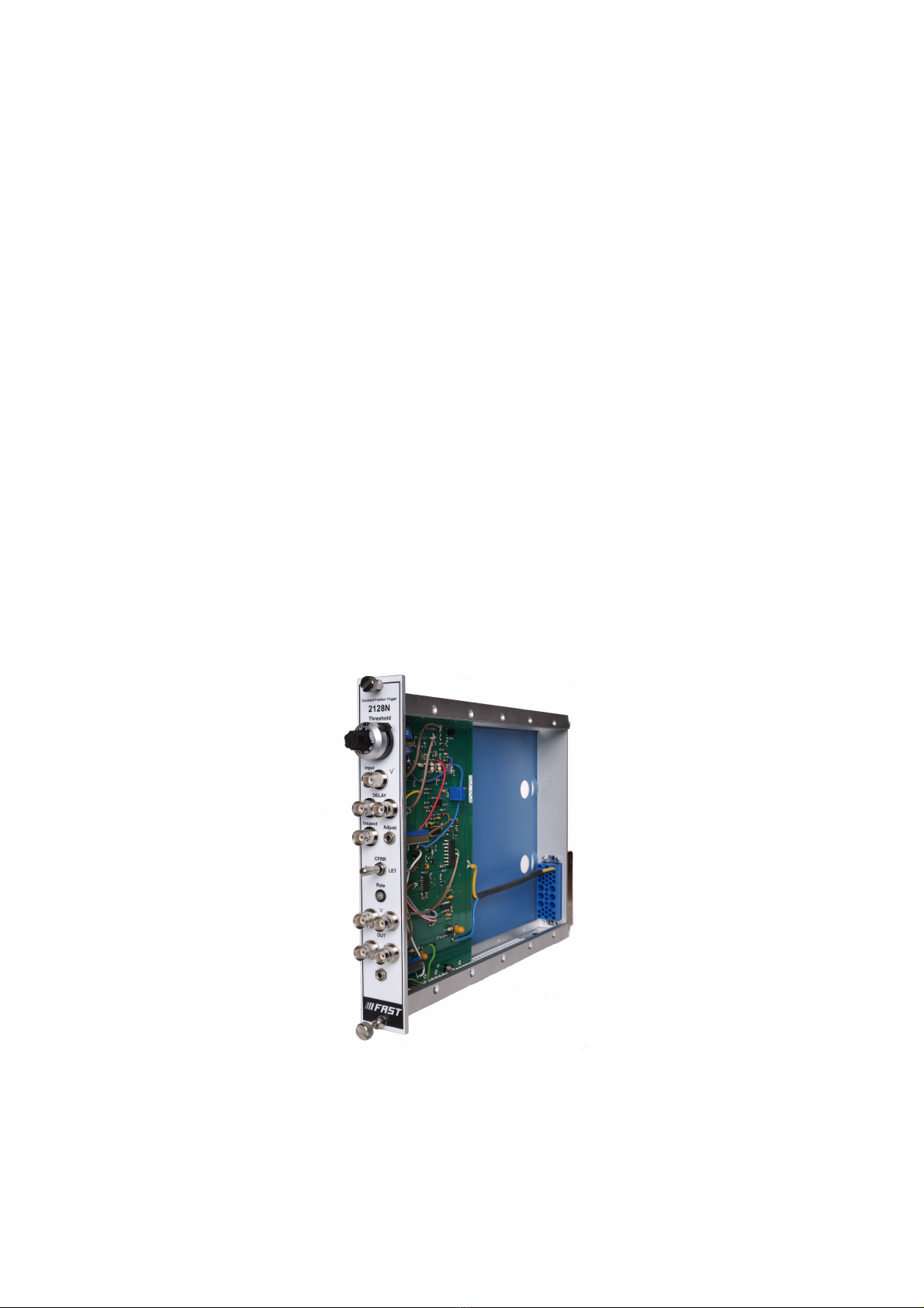
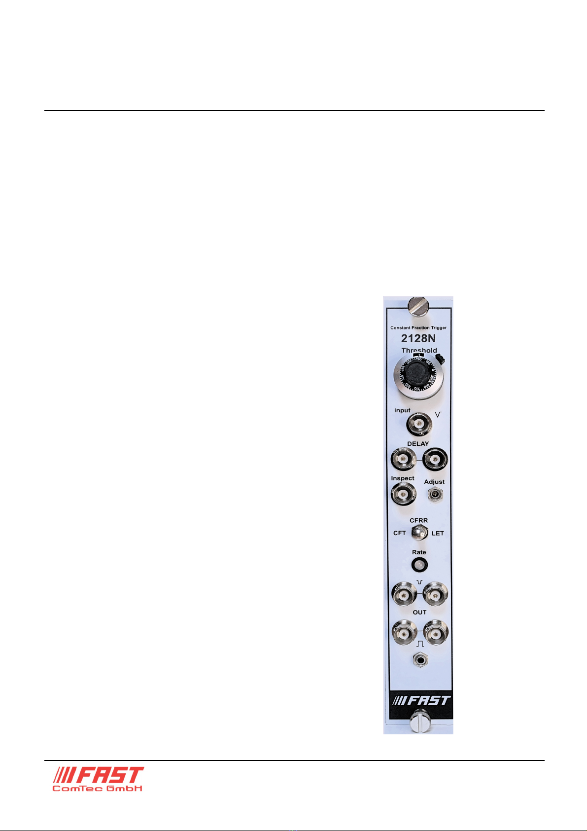
Inputs
Input: - accepts -5 mV to about -3.0 V linear
pulses: width > 1ns, Zin = 50 Ohms, dc
coupled; front panel BNC connector.
Delay: two front panel BNC connectors
accept 50 Ohm delay cable in order to form
the internal constant fraction signal.
Outputs
Inspect displays signal of zero crossing
discriminator for use in trimming time walk.
Neg output two independent negative
current outputs, each providing -32 mA into
50Ω, risetime < 3 ns, pulsewidth 5 ns nominal,
dc coupled.
Pos output two independent positive voltage
outputs, providing 2 V (minimum into 50Ω,
risetime < 10 ns, width adjustable by front
panel width trimming potentiometer, which
also determines the internal dead time.
Controls
Threshold Front panel 10-turn locking dial
potentiometer to set acceptance threshold for
input pulses (range ≈ -5 mV to -1 V .
Adjust front panel trimming potentiometer
(screwdriver to compensate walk of the
internal zero crossing discriminator
Leading edge width of the leading edge
signal is internally set by the trimming
potentiometer on the printed board to 20 ns.
CFRR-CFT-LET Frontpanel three-position
switch to select constant fraction with slow rise
time reject (CFRR , basic constant fraction
(CFT , or leading edge timing (LET modes of
operation.
OUTPUT WIDTH Front panel 22-turn
screwdriver adjustable potentiometer to set
width of slow positive output pulse, which is
equal to the internal dead time of the
discriminator – max setting: 1.5 micro sec.
PERFORMANCE
Dynamic range 1000 : 1
CF mode Walk < ±50ps (typically +30ps
for -30mV to -3V range with <2ns rise time.
Count rate up to 100 MHz, limited by dead
time (OUTPUT WIDTH setting
Pulse pair resolution <10 ns, or as limited
by dead time.
Threshold stability better than ±0.02% / 0C
(± 200 ppm / 0C
Threshold linearity ± 0.25 % integral
Temperature range 0 0C to + 50 0C
Delay cable typical lengths (RG-58)
for Plastic, NaI and Si (S.B. detectors 0.5m
to 1m,
for Planar Germanium detectors 1m to 2m
for Coaxial Ge 2.0 to 4m
Typical Power requirements
Standard version
+6.0V 150mA
-6.0V 450 mA
Physical
Si e single width 1/12 NIM module
(3.43 x 22.13 cm; 1.35 x 8.71 inches as per
TID – 20893 (rev.
Net weight 0.7 kg (2.0 lbs
Options
- can be modified to accept positive pulses
- 12V Version available on request
- on request 220 V (ac / 110V (ac
independent from a NIM bin
- Output width for negative output can be
modified
- threshold setting supplied externally via rear
panel connector
- signal shaping using small fractions and RC
shaping by modifying f and capacitors.