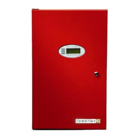
Fike Epaco Bedienungsanleitung

User’s Manual
P/N E06-091, Rev. 0
January 2010
EXPLOSION PROTECTION (ACTIVE) CONTROL SYSTEM

DEVELOPED BY Fike
704 SW 10th Street
P.O. Box 610
Blue Springs, Missouri 64013 U.S.A.
Phone: (888) 628-FIKE (3453)
(816) 229-3405
Fax: (866) 211-9239
COPYRIGHT NOTICE Copyright 2010, All rights reserved.
Fike copyrights this manual and products it describes. You may not reproduce,
transmit, transcribe, or any part of this manual without express, written
permission from Fike.
This manual contains proprietary information intended for distribution to
authorized persons or companies for the sole purpose of conducting business
with Fike. If you distribute any information contained in this manual to
unauthorized persons, you have violated all distributor agreements and we may
take legal action.
TRADEMARKS Fikeis a registered trademark of Fike.
QUALITY Fike has maintained ISO 9001 certification since 1996. Prior to shipment, we
thoroughly test our products and review our documentation to assure the highest
quality in all respects.
WARRANTY Fike provides a one-year limited manufacturer’s warranty on this product. All
warranty returns must be returned from an authorized Fike Distributor. Contact
Fike’s Marketing department for further warranty information.
Fike maintains a repair department that is available to repair and return existing
electronic components or exchange/purchase previously repaired inventory
component (advance replacement). All returns must be approved prior to return.
A Material Return Authorization (MRA) number must be indicated on the box of
the item being returned. Contact the appropriate Regional Sales Manager for
further information regarding product return procedures.
LIMITATIONS OF LIABILITY Installation in accordance with this manual, applicable codes, and the
instructions of the Authority Having Jurisdiction is mandatory. Fike can not be
held liable for any incidental or consequential damages arising from the loss of
property or other damages or losses resulting from the use or misuse of Fike
products beyond the cost of repair or replacement of any defective components.
Fike reserves the right to make product improvements and change product
specifications at any time.
While every precaution has been taken during the preparation of this manual to
ensure the accuracy of its content, Fike assumes no responsibility for errors or
omissions.

EPACO USER’S MANUAL
Revision Date: January, 2010 P/N E06-091 (Rev 0)
REVISION HISTORY
Document Name: EPACO USER’S MANUAL
Original Release Date:..................................................................................................................January, 2010
Revision / Description of Change Revision Date

EPACO USER’S MANUAL
P/N E06-091 (Rev 0) Revision Date: January, 2010
TABLE OF CONTENTS
SECTION PAGE NO.
1.0 INTRODUCTION.......................................................................................................................................... 1
1.1 PRODUCT SUPPORT ................................................................................................................................. 1
1.2 SAFETY INFORMATION ............................................................................................................................. 1
1.3 RELATED DOCUMENTATION .................................................................................................................... 2
2.0 EPACO™ SYSTEM OVERVIEW................................................................................................................. 3
2.1 EXPLOSION PROTECTION CONTROLLER.............................................................................................. 4
2.1.1 OPERATION.............................................................................................................................................. 5
2.1.2 EPC DIAGNOSTICS ................................................................................................................................. 6
2.1.3 EPC SPECIFICATIONS ............................................................................................................................ 7
2.2 POWER SUPPLY UNIT ............................................................................................................................... 8
2.2.1 OPERATION.............................................................................................................................................. 8
2.2.2 PSU DIAGNOSTICS ................................................................................................................................. 9
2.2.3 PSU SPECIFICATIONS .......................................................................................................................... 10
2.2.4 PSU VOLTAGE CHART.......................................................................................................................... 11
2.3 ANNUNCIATOR MODULE........................................................................................................................ 12
2.3.1 OPERATION............................................................................................................................................ 12
2.3.2 AM SPECIFICATIONS ............................................................................................................................ 14
2.4 RELAY CARD MODULE ........................................................................................................................... 15
2.4.1 OPERATION............................................................................................................................................ 15
2.4.2 RC8 LED DIAGNOSTICS........................................................................................................................ 15
2.4.4 RC8 SPECIFICATIONS .......................................................................................................................... 16
3.0 MAINTENANCE......................................................................................................................................... 17
3.1 ROUTINE INSPECTION ............................................................................................................................ 17
4.0 DECOMMISSIONING PROCEDURE....................................................................................................... 18
APPENDIX A-RC8 MODULE STATUS CODES.............................................................................................. 19
APPENDIX B–ANNUNCIATOR MODULE DISPLAY HISTORY CODES........................................................ 24
APPENDIX C-PRESSURE CORRELATION CHART ...................................................................................... 25

EPACO USER’S MANUAL
Revision Date: January, 2010 P/N E06-091 (Rev 0) Page: 1
1.0 INTRODUCTION
This manual is intended for those individuals who are responsible for the interfacing with Fike’s EPACO
explosion protection system. The first-time operator should thoroughly read and understand the instructions
contained within this manual before interfacing with the EPACO system components.
1.1 PRODUCT SUPPORT
If you have any questions or encounter a problem not covered in this manual, you should first try to contact
the Fike Explosion Protection distributor that installed the system as noted below.
For technical support, please contact:
Company Name: _________________________________________
Phone Number: _________________________________________
Fax Number: _________________________________________
E-Mail Address: _________________________________________
If you can not locate the distributor, please call Fike Customer Service using the numbers indicated bellow for
assistance in locating your nearest distributor, or go to our web-site at www.fike.com.
Fike Blue Springs, USA
Phone: +1-816-229-3405
+1-800-979-FIKE (3453)
Option 23 Explosion Protection Support
Fax: +1-816-229-0314
Or
Fike Europe
Phone: +32-14-21-00-31
Fax: +32-14-21-07-43
1.2 SAFETY INFORMATION
Important safety admonishments are used throughout this manual to warn of possible hazards to persons or
equipment.
aWARNING
Warnings are used to indicate the presence of a hazard
which will or may cause personal injury or death, or loss of
service if safety instructions are not followed or if the hazard
is not avoided.
ICaution
Cautions are used to indicate the presence of a hazard
which will or may case damage to the equipment if safety
instructions are not followed or if the hazard is not avoided.
LNotes: Notes indicate the message is important, but is not
of a Warning or Caution category. These notes can be of
great benefit to the user and should be read.

EPACO USER’S MANUAL
Page: 2 P/N E06-091 (Rev 0) Revision Date: January, 2010
1.3 RELATED DOCUMENTATION
Document Title Part Number
EPACO System, Explosion Protection Controller (EPC) Installation and Operation Manual E06-051
EPACO System, Explosion Protection Controller (EPC) Solenoid Installation and Operation
Manual E06-090
EPACO System, Power Supply Unit (PSU) Installation and Operation Manual E06-052
EPACO System, Annunciator Module (AM) Installation and Operation Manual E06-053
EPACO System, Relay Card (RC8) Installation and Operation Manual E06-054

EPACO USER’S MANUAL
Revision Date: January, 2010 P/N E06-091 (Rev 0) Page: 3
2.0 EPACO™ SYSTEM OVERVIEW
The EPACOexplosion detection and control system is comprised of explosion detectors, control unit (EPC),
power supply unit (PSU), optional annunciator module (AM) and relay cards (RC8). EPACOcombines the
latest in addressable technology with simplicity of installation and maintenance. All system modules are DIN
rail mounted to allow for a variety of installation options. Three (3) bus type communication circuits tie the
various system modules into one easy to operate protection system. A non-volatile history buffer allows for
enhanced diagnostic ability to troubleshoot process situations. The optional Annunciator Module (AM), the
customer has the ability to step through a menu format to retrieve process history without having to wait for a
service agency to arrive on site.
EPACOis designed to detect and control any of Fike’s Active explosion suppression and isolation systems;
which range from chemical suppression, mechanical isolation (gate and pinch valve), chemical isolation or
any combination thereof. Detection is achieved by either pressure and/or flame radiation detectors designed
to sense the incipient explosion and trigger the explosion suppression and/or isolation systems.
EPACO System Block Diagram
2A2A2A2A2A2A
RC8 AMEPC-3 EPC-4EPC-1 EPC-2
24VDC
VOLTAGE
25VAC
OUTPUT
DB9
24VDC
DB9
ADD
2A
2
4
1
3
24VDC
6
DB9
5
ADD MODE
78
2A
1
2
34
- 2A -
DB9
ADD MODE
24VDC
2A
R
EIGHT (8) PROGRAMMABLE RELAYS
NEMA ENCLOSURE
ALARM RELAY
TROUBLE/SUPERVISORY RELAY
SERIES FIRING CIRCUIT UP
TO (6) RELEASING DEVICES
CHEMICAL
ISOLATION MECHANICAL
ISOLATION
SUPPRESSION
CONTAINER
GATE VALVE
DETECTION
CIRCUIT #2
DETECTION
CIRCUIT #1
SYSTEM DISABLE INPUT
SUPERVISORY INPUT
CONTACT CLOSURE INPUT
OR DETECTION CIRCUIT #3
XFMR
BATTERY BATTERY
NOTES:
1. MAXIMUM OF FOUR (4) EPC'S PER EPACO
SYSTEM. EACH CAPABLE OF SUPPORTING TWO
4-20 mA DETECTORS.
2. CAPABLE OF SUPPLYING POWER TO FOUR (4)
RELAY CARDS, FOUR (4) EPC CONTROLLERS AND
ONE (1) ANNUNCIATOR MODULE.
3. CAPABLE OF SUPPORTING FOUR (4) RELAY
CARDS, FOUR (4) EPC CONTROLLERS AND ONE
(1) POWER SUPPLY UNIT.
4. MAXIMUM OF FOUR (4) RELAY CARDS PER
ANNUNCIATOR MODULE.

EPACO USER’S MANUAL
Page: 4 P/N E06-091 (Rev 0) Release Date: January, 2010
2.1 EXPLOSION PROTECTION CONTROLLER
The Explosion Protection Controller (EPC) is the cornerstone of
the EPACOsystem. The EPC is an addressable panel that has
the ability to retain an event history for enhanced system
diagnostics. The EPC is DIN rail mounted which allows mounting
of the controller in close proximity to the protected environment,
thereby minimizing field wiring. Shorter wire runs greatly reduce
the interference from electrical and radio frequency sources,
allowing for a much more reliable protection system.
The EPC’s detection inputs can be programmed for pressure
warning, threshold detection, and rate of rise detection. It also
has a contact closure detection circuit to support thermal, infrared,
or other switch-closure type detection devices. A supervisory
input circuit is provided to monitor suppression container pressure
or other similar system status safeguards. The EPC has a remote
disable input contact to allow for disabling the EPC from a
customer PLC or other remote device during product loading,
cleaning, or maintenance. An RS232 connection is available at
each module for connection to a PC. Using the EP WorksTM
software, an authorized user can access system diagnostics and
perform complex programming by PC.
The following tasks are accomplished by the EPC:
Monitors all supervised circuits for wiring faults (Open, Short, or Activation)
Two detection circuits are monitored on a 250 micro second (0.25 msec) rate and examined for rate
of rise and threshold levels
When activation requirements are met by the detection circuit, it activates the series firing output
within 2 milli-seconds
Communicates system status to other EPC’s connected locally so that they can respond within 4 milli-
seconds
Communicates system status to Annunciators and Relay Control Modules for user interface

EPACO USER’S MANUAL
Release Date: January, 2010 P/N: E06-091 (Rev 0) Page: 5
2.1.1 OPERATION
The EPC is equipped with three (3) colored LEDs that provide instant visual indication of system status. EPC
operation can be classified into three main states: Normal, Trouble and Alarm. A general description of each
state is described below.
EPC Normal State
When power is applied to the EPC, it performs a 4 second initialization. At the
end of the initialization, the trouble LED blinks slow and the local piezo beeps in
long recurring sound. It can then enter the “NORMAL” state if the power is of an
appropriate voltage and there are no troubles or alarms. In the Normal State the
green Power LED is ‘ON’, the local piezo is ‘OFF’, the trouble and alarm relays
are energized. All other LED’s are ‘OFF’.
EPC Trouble State
A trouble occurs on the EPC if any one of the supervised circuits experiences a
wiring fault open or short condition, if the EPC configuration is invalid, if the
system is disabled, if a process pressure warning level is exceeded, or if the input
voltage drops below 18VDC. In the Trouble State the yellow Trouble LED is ‘ON’,
the local piezo is ‘ON’, and the P6 trouble relay is de-energized. Depending on
the cause of the trouble, the system may or may NOT be completely functional.
Each trouble should be investigated to determine the cause and promptly fixed.
Each trouble, except for remote disable, will latch at the EPC. If the trouble is
resolved, the EPC trouble can be cleared by disabling and re-enabling via the
remote disable input, by cycling of the power input to the EPC, or by disabling
and re-enabling the EPC via the Annunciator Module. If the remote disable is
active, the EPC will enter the trouble state. When the remote disable is returned
to normal, the EPC will automatically clear to the normal state, if no other troubles
are present, without cycling the power.
EPC Alarm State
When the detection circuits have exceeded the alarm conditions required by the
configuration, the EPC enters the Alarm State. In the Alarm State the red Alarm
LED is ‘ON’, the local piezo ‘ON’, the Alarm relay is de-energized, and the series
firing output is activated. The alarm state is latching. If the alarm is cleared, the
EPC requires cycling of the power input to clear the alarm.
Red
24VDC
Green
Yellow

EPACO USER’S MANUAL
Page: 6 P/N E06-091 (Rev 0) Release Date: January, 2010
2.1.2 EPC DIAGNOSTICS
In addition to the EPC’s three system status LEDs, an integral buzzer is provided to assist in diagnosing
problems with the system. The following table identifies how the LEDs and buzzer will operate in response to
expected system events.
Power
LED
on
on
on
on
on
on
on
on
on
on
on
on
on
Piezo
off
long-short
pulse
short-short
pulse
long
pulse
off
on not
latched
off
on
off
on
off
on not
latched
off
Trouble
LED
on
on
on
blink slow
off
on latched
on
on (1)
on
on
off
on latched
no change
Trouble
Relay
De-energized
De-energized
De-energized
De-energized
Energized
De-energized
latched
De-energized
De-energized
(1)
De-energized
De-energized
Energized
De-energized
latched
no change
Alarm Relay
De-energized
De-energized
De-energized
Energized
Energized
Energized
Energized
De-energized
Energized
Energized
Energized
Energized
no change
Alarm LED
off
slow blink
off
off
off
off
off
on
on
on
fast blink
off
off
Condition
Initial power up [first 4 seconds]
Power up in an alarm state
Invalid configuration or
Prevent restart after activation
Initializing [follows initial power up]
Normal State
Trouble State
Disabled State
Alarm State
Disabled State & alarm
Return to Armed from previous state
1st alarm in AND configuration
[cross zoned]
Warning pressure level
PC mode
(1) Trouble relay and LED following trouble condition on series firing output due to release action.
Inhaltsverzeichnis
Andere Fike Steuerungssystem Handbücher

Fike
Fike CyberCat 1016 Handbuch

Fike
Fike CyberCat 50 10-070 Handbuch

Fike
Fike Cheetah Xi Benutzerhandbuch

Fike
Fike FIK-CZ-6 Bedienungsanleitung

Fike
Fike CyberCat 1016 Bedienungsanleitung

Fike
Fike 10-071 Bedienungsanleitung

Fike
Fike 10-2539 Betriebsanleitung

Fike
Fike Cheetah Xi Bedienungsanleitung

Fike
Fike FIK-PULL-SA Bedienungsanleitung

Fike
Fike 55-042 Bedienungsanleitung