Firstech T5R5GB Bedienungsanleitung

—1—
preface
First of all, thank you for buying a high-performance universal frequency converter!
This is a general high-performance current vector inverter to control the AC asynchronous
motor, which can be used for textile, paper, wire drawing, machine tools, packaging, food, fans,
water pumps and a variety of automated production equipment to drive.
This manual introduces the functional characteristics and use methods of high-performance
general frequency converter, including product selection, parameter setting, operation debugging,
maintenance inspection, etc. Please read this manual carefully before use. The equipment
supporting manufacturer should send this manual to the end user along with the equipment to
facilitate the subsequent use of reference.
matters need attention
To illustrate the detailed part of the product, the legend in this specification is sometimes the status of the
cover or safety cover.
When using this product, be sure to install the shell and cover according to the instructions.
The legend in this instruction are for illustration only and may differ from the product you order.
The company is committed to continuous product improvement, functionality and upgrading, and the
information provided is subject to change without notice.
If you have problems with your use, please contact our regional agents, or contact our customer service
center directly

Directory High Performance Universal frequency Converter User Manual
— 2 —
catalogue
Chapter I Safety Notes..............................................................................................................................................3
1.1 Safety matters.............................................................................................................................................. 3
Chapter II: Product Information.............................................................................................................................6
2.1 Nnameplate and model description......................................................................................................6
2.2 Product Series Description....................................................................................................................... 6
2.3 Product Technical Specifications............................................................................................................ 7
Chapter III: Electrical Installation........................................................................................................................... 9
3.1 Overall size and installation hole position of the frequency converter...................................... 9
3.2 Wiring........................................................................................................................................................... 10
Chapter 4: Keyboard Display and Operation................................................................................................... 13
4.1 Introduction of the L E D keyboard interface................................................................................... 13
4.2 Description of function code viewing and modification method.............................................. 14
Chapter V Functional Parameter Table.............................................................................................................. 15
Chapter VI Fault Diagnosis and Countermeasures........................................................................................ 49
Chapter VII. The Modbus Communication Agreement................................................................................ 53
Chapter VIII Special Parameter Group for Continuous Pressure Water Supply (with hibernation).62
Appendix to the Warranty Agreement.............................................................................................................. 63
Product Warranty Card...........................................................................................................................................64

High Performance Universal Inverter User Manual Chapter I Safety Precautions
— 3 —
Chapter I Safety Notes
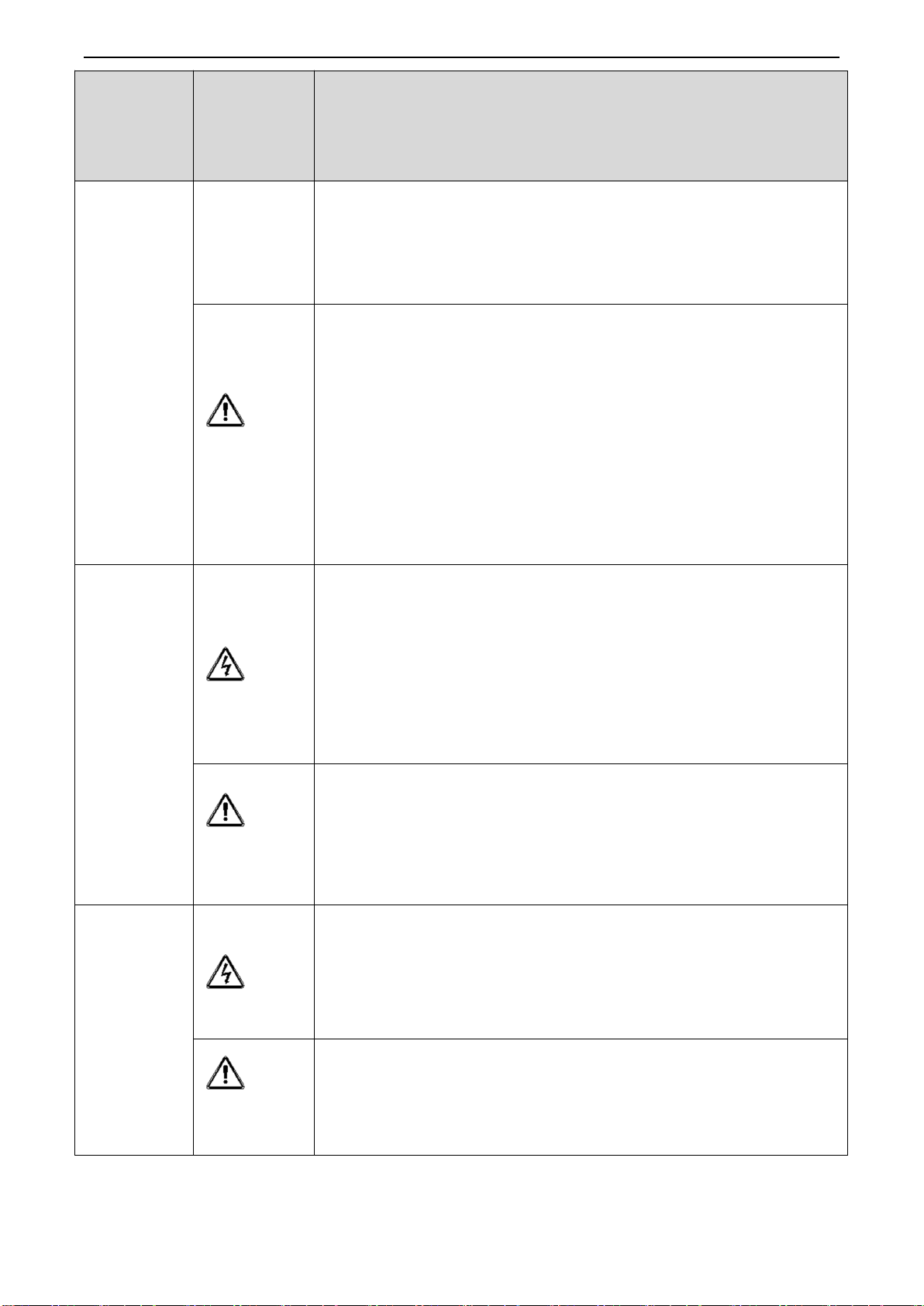
Safety definition: In this manual, the safety precautions are divided into the following two categories:
Hazanger: serious injury or even death.
Note: The danger caused by no required operation may lead to moderate or minor injuries, and
equipment damage.
When installing, commissioning and repairing the system, please read this chapter carefully and be sure
according to the safety precautions required in this chapter. Any damage or loss caused by the illegal operation is
not related to the Company.
1.1 Safety matters
Use the
stage
security
classification
item
Before
installation
danger
When unpacking the packing water, parts are missing or damaged,
please do not install!
When the outer package logo does not comply with the physical name,
please do not install it!
pay
attention to
Handling should be carried lightly and put gently, otherwise there is a
danger of damage to the equipment!
Do not use damaged drives or missing drives, there is a risk of injury!
Do not touch the components of the control system by hand, otherwise
there is a danger of static damage!
When
installing
danger
Please install on flame retardant objects such as metal away from
combustible, otherwise fire may alarm!
pay
attention to
Do not let the wire head or screw fall into the drive, otherwise cause
drive damage!
Install the drive where there is less vibration to avoid direct sunlight.
When the driver is placed in a closed cabinet or closed space, please pay
attention to the installation gap to ensure the heat dissipation effect.
When wiring
danger
The instructions of this manual must be followed and used by
professional electrical engineers, otherwise unexpected dangers will
occur!
There must be a circuit breaker separated between the drive and the
power supply, otherwise a fire alarm may occur!

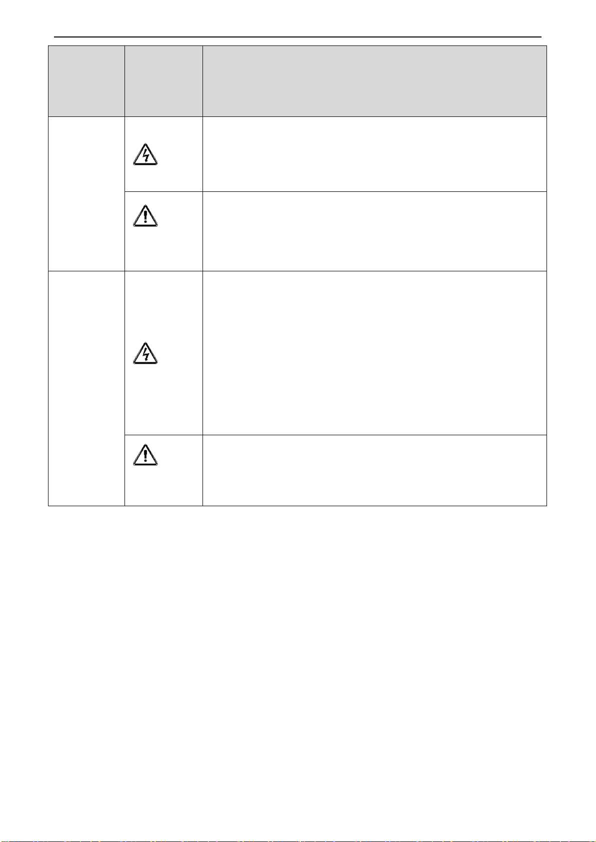
Chapter I Safety Notes High Performance General Converter User Manual
— 4 —
Use the
stage
security
classification
item
Ensure that the power supply is at zero energy before wiring, otherwise
there is a danger of electric shock!
Please ground the drive properly according to the standard, otherwise
electric shock risk!
pay
attention to
Never connect the input power to the output terminal of the drive (U, V,
W). Note the mark of the terminals, do not connect the wrong line!
Otherwise, cause drive damage!
The brake resistance must not be connected directly between the DC
bus + and-terminals. Otherwise, it will cause a fire!
Refer to the recommendations in the manual. Otherwise, an accident
may occur!
Do not remove the connection cables inside the drive, otherwise it may
cause damage inside the drive.
Before the
electricity
danger
Please confirm that the voltage level of the input power supply is
consistent with the rated voltage level of the driver; the wiring position
on the power input terminal (R, S, T) and output terminal (U, V, W) is
correct; and check whether the peripheral circuit connected to the driver
is fastened, otherwise the drive is damaged!
Any part of the drive is not subjected to withstand pressure test from the
factory. Otherwise, it may cause an accident!
pay
attention to
The drive must be covered before electrification, otherwise it may cause
electric shock!
The wiring of all peripheral accessories must follow the instructions of
this manual and correctly follow the circuit connection method provided
in this manual. Otherwise, it may cause an accident!
After the
electricity
danger
Do not open the cover plate after the power supply, otherwise there is a
danger of electric shock!
If the indicator light does not turn on and the keyboard does not display,
please turn off the power switch immediately, do not touch any input and
output terminal of the drive, otherwise there is a danger of electric shock!
pay
attention to
If parameter identification is required, please eliminate the possible risk
of injury during motor rotation!
Do not change the drive manufacturer parameters, otherwise equipment
damage may occur!

High Performance Universal Inverter User Manual Chapter I Safety Precautions
— 5 —
Use the
stage
security
classification
item
in service
danger
Do not touch the cooling fan, radiator and discharge resistance to test
the temperature, otherwise it may cause burns!
Non-professional technicians do not detect signals during operation,
otherwise it may cause personal injury or equipment damage!
pay
attention to
During drive operation, something should avoid falling into the device,
otherwise it will cause equipment damage!
Do not use the contactor on-break method to control the drive start and
stop, otherwise it will cause equipment damage!
Maintenance
danger
Do not repair and maintain the equipment with live power, otherwise
there is a danger of electric shock!
Cut off the input power supply for 10 minutes, the drive can be
maintained and repaired, otherwise the residual charge on the capacitor
will cause damage to people!
Without professional training do not repair and maintain the drive,
otherwise personal injury or equipment damage!
All pluggable plug-ins must be plugged under power failure!
Parameters must be set and checked after replacing the drive.
pay
attention to
Before maintaining the drive, ensure that the motor is disconnected from
the drive to prevent the motor from returning electricity to the driver due
to accidental rotation.

Chapter II Product Information High-performance General Inverter User Manual
— 6 —
Chapter II: Product Information
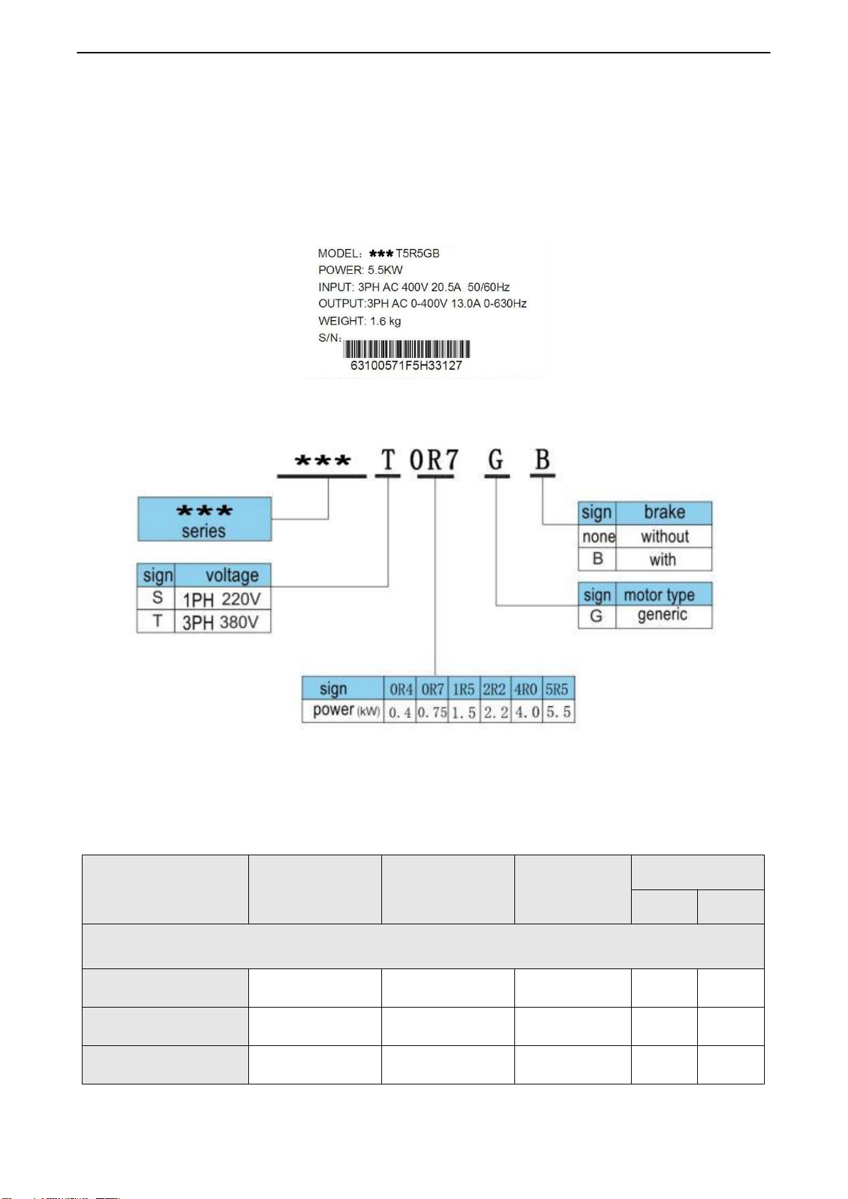
2.1 Nnameplate and model description
data plate:
Figure 2-1 The nameplate
demonstration of the type:
Figure 2-2 Model Description
2.2 Product Series Description
Table 2-1 Model and technical data of high-performance general frequency converter
Frequency converter
model
Power capacity
(K VA)
input currenton
(A)
output
(A)
Adaptation motor
K W
HP
Single-phase power supply: 220V, 50 / 60Hz
***S 0R 4GB
1
8.2
4.0
0.4
0.5
***S 0R 7GB
1.5
8.2
4.0
0.75
1.0
***S 1R 5GB
3.0
14.0
7.0
1.5
2.0

High Performance Universal FrequConverter User Manual Chapter II Product Information
— 7 —
Frequency converter
model
Power capacity
(K VA)
input currenton
(A)
output
(A)
Adaptation motor
K W
HP
Three-phase power supply: 380V, 50 / 60Hz
***T 0R 7GB
1.5
3.4
2.1
0.75
1
***T 1R 5GB
3.0
5.0
3.8
1.5
2
***T 2R 2GB
4.0
5.8
5.1
2.2
3
***T 4R 0GB
5.0
10.5
9.0
4.0
4
***T 5R 5GB
8.9
14.6
13.0
5.5
7.5
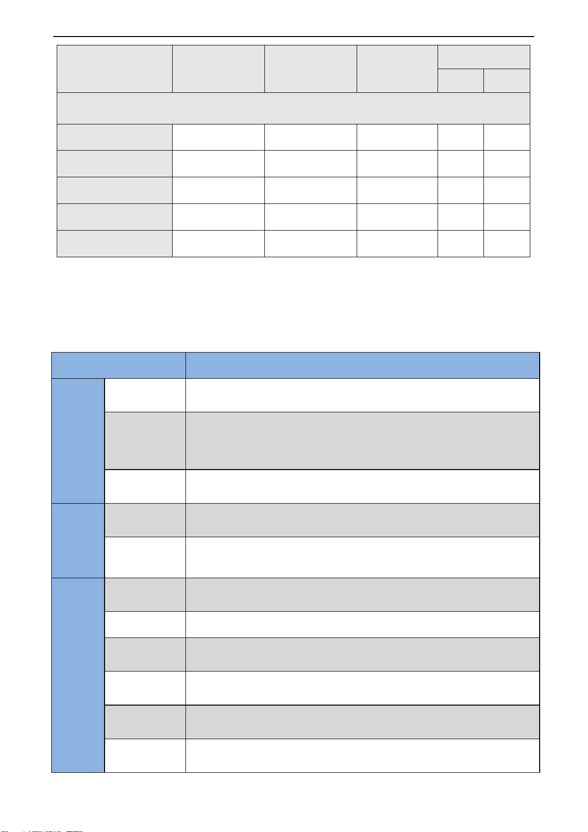
2.3 Product Technical Specifications
Table 2-2 Technical specifications of high-performance general-purpose inverter
project
specifications
source
Input power
voltage
Single-phase / 3-phase 220V model: 200V ~240V
Three-phase 380V model: 380V ~440V
Voltage
allowable
fluctuation
range
-15%~10%
Input power
frequency
50Hz or 60Hz, with a fluctuation of less than 5%
output
maximum
output voltage
Phase 3:0~ Input voltage
overload
capacity
150% rated output current for 60 seconds, 180% rated output current for 10
seconds, and 200% rated output current for 1 second
accuse
make
particular
nature
control method
VVVF control
Speed sensor-free vector control (FOC Sensorless)
running mode
Speed control, torque control (FOC Sensorless)
Speed range
1:100(VVVF )
1:200(FOC Sensorless)
Speed control
accuracy
±0.5% (VVVF )
±0.2% (FOC Sensorless)
Speed response
5Hz(VVVF )
20Hz(FOC Sensorless)
Frequency
control range
.000~630.00Hz

Chapter II Product Information High-performance General Inverter User Manual
— 8 —
Input the
frequency
resolution
Digital input: 0.01Hz
Analog input: 0.1% of the maximum frequency
starting torque
150%/0.5Hz (VVVF )
150%/0.25Hz(FOC Sensorless)
Torque control
accuracy
FOC Sensorless:10%
VVVF
characteristic
VVVF curve type: straight line, multipoint, power function, V / F separation;
Torque lifting support: automatic torque lifting (factory setting), manual torque
lifting
Frequency given
the slope
Support straight line and S-curve increase and deceleration;
4 Groups of acceleration and deceleration time, with a set range of 0.0s ~3600.0s
DC bus voltage
control
OVC (bus overvoltage control), LVC (bus undervoltage control)
carrier frequency
1K Hz ~15K Hz
starting mode
Direct start (superimposed DC brake); speed tracking start
Stop the way
Reducate stop (DC brake); free stop
function
communication
MODBUS communication
input terminal
Five digital input terminals, one of which is a high-speed pulsed HDI input
Two analog quantity input terminals;
leading-out
terminal
2 Digital output terminals;, one of which is a high-speed pulse HDO output
Two relay output terminals;
One analog output terminal, supporting 0~20mA current output or 0~10V
voltage output;
protect
Protection function, see Chapter 6, Fault Analysis and Handling
environment
Where to use
Indoor, free from direct sunlight, no dust, corrosive gas, combustible gas, oil mist,
water vapor, dripping water or salt, etc
above sea level
At 0 ~ 3,000 m. More than 1000 meters should be used, every 100 meters
increased, the rated output current reduced by 1%
ambient
temperature
-10℃ ~ + 40℃, up to 50℃. From 40℃, the rated output current was reduced by
1.5% for every 1℃ increase
humidity
Less than 95%RH, no condensation
vibrate
Less than 5.9 m/s2(0.5g)
storage
temperature
-20℃~+60℃
else
way to install
Wall-mounted type, floor electric control cabinet type, wall-permeable type
levels of
protection
IP20
cooling-down
method
forced air cooling

High Performance General Frequency converter User Manual Chapter 3 Electrical Installation
— 9 —
Chapter III: Electrical Installation
3.1 Overall size and installation hole position of the frequency converter
Figure 3-1 Keyboard and opening dimensions
Figure 3-2 Outline dimensions of frequency converter
product model
Installation
hole position
(mm)
outline dimension (mm)
Installation
aperture
Net
quantity
remarks
A
B
H
W
D
(mm)
(Kg)
Single phase 220V
***S0R4GB
67.5
157
170
85
140
φ5.0
1.28
D
potentiometer
Knob height
10mm
***S0R7GB
***S1R5GB
Three phase 380V
***T0R7GB
67.5
157
170
85
140
φ5.0
1.28
D
potentiometer
Knob height
10mm
***T1R5GB
***T2R2GB
***T4R0GB
85
185
195
100
155
φ5.0
1.57
D
potentiometer
Knob height
***T5R5GB

Chapter III User Manual for High Performance Electrical Inverter
— 10 —
Table 3-1 High Performance General Outline Dimensions and Installation Size
3.2 Wiring
3.2.1, standard wiring diagram
Figure 3-3 Standard wiring diagram (K2 relay is not installed by default and can be selected according to customer
requirements)
3.2.2 Main circuit wiring terminal
1) Description of the main loop terminal of the single-phase frequency converter:
Inhaltsverzeichnis