Genvex ECO 400 XL Bedienungsanleitung
A
INSTALLATION
MANUAL
ECO 400 XL
Mechanical ventilation with passive heat
recovery

2
SafetyiInformation .................................................................................................................................................................3
Functional description...........................................................................................................................................................4
Installation ................................................................................................................................................................................5
Technical drawing.........................................................................................................................................................6
Duct connection............................................................................................................................................................7
Duct system ...................................................................................................................................................................7
Condensation water drain.........................................................................................................................................8
Insulation of ducts in cold attics ............................................................................................................................9
Insulation of ducts in heated rooms...................................................................................................................10
Reheating supply air.................................................................................................................................................10
Preheating outdoor air............................................................................................................................................11
Electrical installation...............................................................................................................................................11
Control and calibration of the system...............................................................................................................11
Optimal initial calibration of the system..........................................................................................................12
System maintenance................................................................................................................................................12
Recommended maintenance intervals..............................................................................................................14
Spare parts..............................................................................................................................................................................15
Trouble shooting....................................................................................................................................................................16
Safety thermostat in electric heating surface (accessory)........................................................................16
System not running....................................................................................................................................................16
No supply air.................................................................................................................................................................16
No exhaust air..............................................................................................................................................................16
Cold supply air.............................................................................................................................................................16
Alerts ..............................................................................................................................................................................16
Electrical diagram – Optima 270 ....................................................................................................................................17
Declaration of conformity.................................................................................................................................................18
TABLE OF CONTENTS

3
This manual also describes installation and service work to
be performed by a professional.
This appliance can be operated by children aged 8 and over,
by persons with reduced physical, sensory and mental
abilities, and by persons with a lack of experience and
knowledge, provided they are supervised or have received
guidance on using the appliance in a safe way and under-
stand the dangers involved. Children must not play with the
appliance. Cleaning and user maintenance must not be
performed by children without supervision.
Subject to design changes.
Labelling
The UKCA/CE mark represents Genvex’s assurance that the
product complies with all regulations for the product in
accordance with relevant UK and EU directives. The
UKCA/CE mark is mandatory for most products sold in
the EU and the UK, irrespective of where they are made.
SAFETY INFORMATION

ECO 400 XL is a horizontally mounted ventilation system
for comfort ventilation in homes and small businesses.
The system is fitted with a high efficiency counter flow
heat exchanger, which recovers heat from exhaust air in the
property and preheats the fresh supply air.
ECO 400 XL can be configured as both right and left hand
facing depending on installation conditions.
An integrated modulating electric preheater can be
selected for the system, which ensures that balanced air
volumes can be maintained – even during periods of very
cold outdoor temperatures.
You can also choose an integrated water level switch, which
ensures the system stops and an alarm is shown on the
display if problems with the condensate drain occur (e.g.,
clogged drain).
ECO 400 XL is designed for installation outside the build-
ing envelope and has low heat loss due to its high heat-
insulating capacity. The system must be installed so that it
is protected from wind and weather.
Where installation conditions permit, the ECO400 XL unit
can also be installed indoors.
4
FUNCTIONAL DESCRIPTION
IMPORTANT:
Follow these instructions when installing the ECO 400 XL:
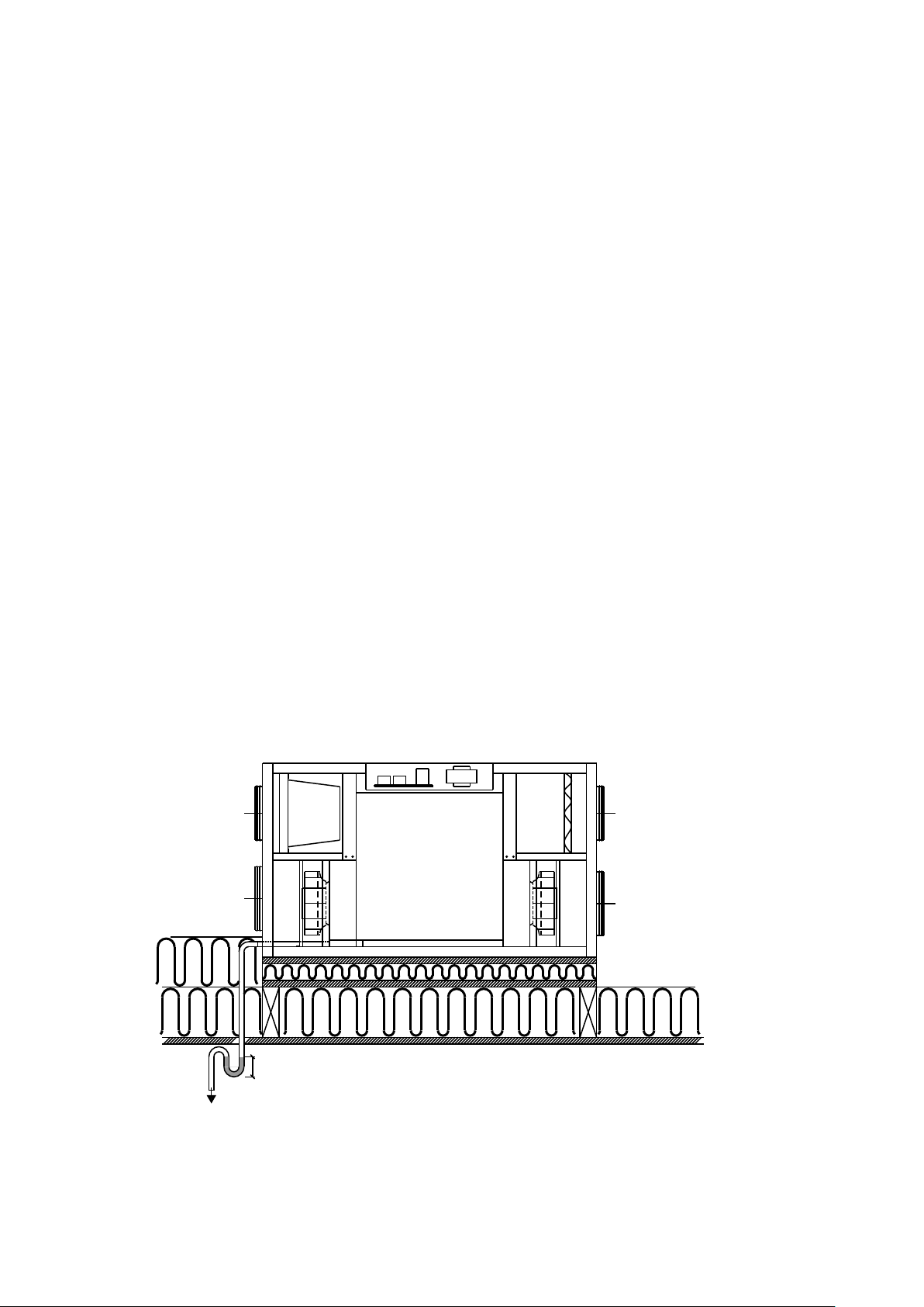
1) The system must be installed to allow the condensation
water to drain freely.
2) An airtight drain trap must be installed in a frost-free
location to compensate for fan pressure.
3) The drain trap must be a minimum of 50 mm in height.
4) Ensure the fall in the drain extends all the way to the
drain outlet.
5) Pour 1 litre of water into the condensate tray of the unit
to check that it drains correctly. Make sure the drain
trap is filled with water every year before beginning to
use the unit.
6) If the drain trap is installed in an area where
temperatures can drop below 0°C, then the drain trap
must be protected against freezing by a thermostat
and an electric heating element that turns on when the
temperature drops below +2C°.
7) The airflow volume for the supply air and exhaust air
must be adjusted before using the unit. It is important
to maintain an air balance inside the house.
8) We recommend closing the ceiling vents, etc., until the
system has been started up and adjusted.
KVM-Genvex A/S always recommends careful planning of
the installation space for your Genvex product in relation to
the location of living spaces. As this is a technical product
that contains fans and/or a heat pump, in rare cases, and in
combination with inappropriate installation conditions, it
may cause unsatisfactory noise or vibration nuisances. As a
rule, we always recommend installing the technical system
so that it is not located in the immediate vicinity of a
bedroom. Furthermore, when securing the Genvex system
to the building structure, it is recommended attaching it to
a heavy structural component such as concrete. It should
also be ensured that no sound or vibrations can be trans-
mitted through materials in contact with the technical
system. If there is a risk of propagation of noise and
vibrations, further installation of vibration-damping
material and sound-damping of installation rooms are
recommended.
100 mm
Vandlås
Til indvendig afløb
UdsugningFriskluft
IndblæsningAfkast
Manglende vand i vandlås =
vandskader
50 mm
Extract air
Supply air
Outdoor air
Discharge
Drain trap
For internal drainage
5
INSTALLATION
The ECO 400 XL is delivered as right-facing (as shown in
the drawing below). If you want the condensate drain at the
opposite end, simply remove the front cover and back panel
on the unit, then install the back panel on the front and turn
the unit 180°.
The unit must be placed on a surface so that vibrations
from the unit are not transmitted down through the ceiling
and walls. As the unit can produce up to 8 litres of conden-
sation water per day during the winter period, the conden-
sate drain, together with the requisite drain trap, must flow
frost-free to the internal drain.
To service and maintain the unit, there must be at least 600
mm of clearance in front of the unit and a surface that can
be walked on. If the unit is placed in the attic, then there
must be free access from the attic hatch to the unit.
Weight: 56 kg
1280699
3
4
586
1
2
83
45
10
590
160
89
5
6
7
11
178254
349,5
1204
15
6
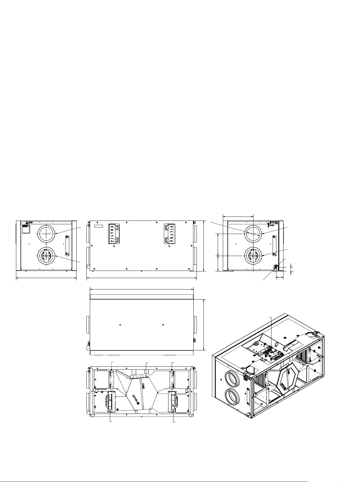
Technical drawing in mm
1. Outdoor air
2. Discharge air
3. Extract air
4. Supply air
5. Heat exchanger
6. Supply air fan
7. Extract air fan
8. Filter outdoor air
9. Filter extract air
10. Condensate drain
11. Electrical connection
3 m
1 m
3 m
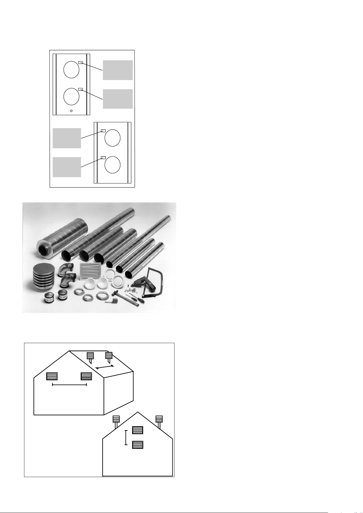
Duct connection
A label is affixed to all duct sockets, indicating which
ventilation ducts should be connected to the various
sockets.
Connect supply air
Duct system from unit to supply air in living room.
Connect extract air
Duct system from wet rooms to the unit.
Outdoor air connected
Duct system from outdoor air intake hood/outdoor air
intake grille from outdoors or from the ground exchanger to
unit.
Discharge is connected
Duct system from unit to exhaust hood/exhaust grille to
open air.
Duct system
It is recommended that the duct system is constructed
using spiral-folded pipes and fittings with rubber ring seals
to achieve a tight and long-lasting duct system.
To achieve a satisfactorily low noise level from the unit,
attenuators must always be fitted to the supply and
exhaust air duct system between the unit and the first
supply and exhaust air fittings.
Air velocities in the ducts should be dimensioned at a
sufficiently low rate so that no noise is generated by the
supply and extract air fittings.
When placing outdoor air and exhaust air hoods/gratings,
care must be taken not to short-circuit the two airflows,
thus causing return air to avoid being sucked back in.
It is recommended that gratings be placed on the north or
east side of the house for optimal comfort in homes/
apartments.
Minimum distance: 3 metres
Outdoor Air
Discharge Air
Extract Air
Supply Air
Drain
7
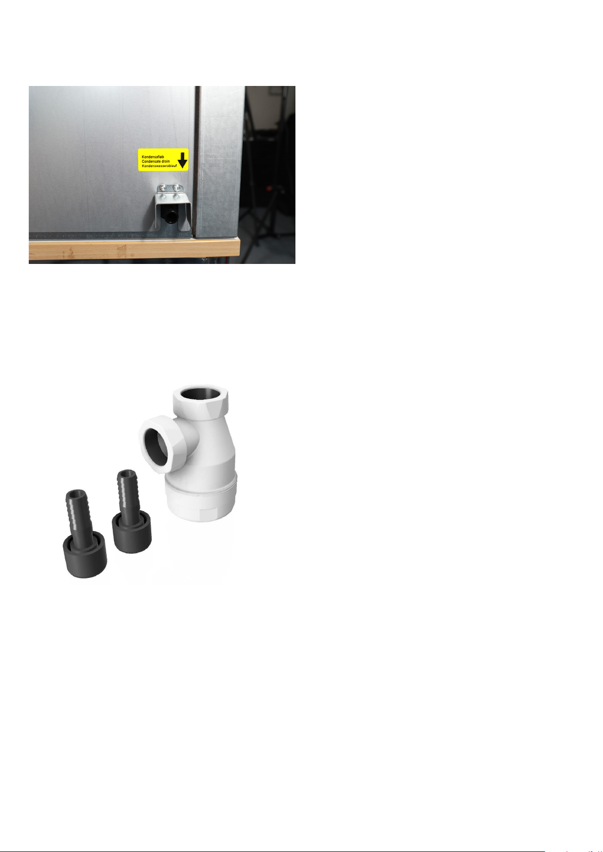
Condensate water drain
Condensate drain
The ventilation unit produces up to 8 litres of condensation
water per day. It is therefore important to mount the
condensate drain correctly. An ordinary Ø15 mm hose can
be connected directly to the ventilation unit.
It is important to make a loop on the hose, so that a drain
trap with a minimum of 50 mm is formed.
Water column
There must be a slope of 1% from the drain trap and the
hose towards the drain. If the unit is installed in a cold
environment the condensate drain must be insulated to
prevent the condensation water in the pipe from freezing.
However, it is recommended that the drain trap is installed
in a heated area to ensure that the water inside it does not
freeze. If installation problems make it impossible to
protect the condensate drain against frost using insulation,
then a thermostatically controlled heating wire must be
installed around the condensate drain. During operation,
the unit experiences internal negative pressure. Therefore,
it is necessary to ensure a water column height of at least
50 mm in the drain trap under all conditions.
If the MVHR unit is installed in a cold attic, the condensa-
tion water drainpipe must be insulated so that the conden-
sation water in the pipe does not freeze.
We also recommend installing the drain trap in a heated
room below to ensure that the water in the drain trap does
not freeze.
If it is not possible to protect the condensation water
drainpipe against freezing by insulating it, then a thermo-
statically controlled heating element must be installed
around the condensation water drainpipe.
When hanging on a wooden wall, a vibration damper is
recommended to avoid vibration transmission.
As an alternative to the looped drain trap, a Genvex univer-
sal drain trap with hose connection can be used, product no.
063289 (see the photo to the left).
8
Ø15 mm condensate water connection on ECO 400 XL
Genvex universal drain trap
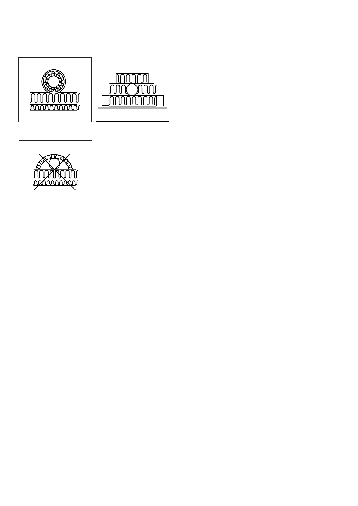
Isolering af kanaler, alt. A
Isolering af kanaler, alt. B
Forkert isolering af kanaler
Insulation of ducts in cold attics
To utilise the full heat recovery capacity of the units, the
ducts must be properly insulated.
Genvex recommends the following:
Supply air and extract air ducts
To minimise heat loss from the duct system in cold attics,
supply and extract air ducts should be insulated with a
minimum of 100 mm insulation. If insulation form alterna-
tive (A) is used, it is recommended that the insulation is
made of 2 x 50 mm lamella mats with paper or aluminum
foil on the outside, and with staggered joints between the 2
insulation layers. If the ducts are laid out on the truss
frame, alternative B can be used. Insulation must always be
tightly wrapped around the ducts.
Outdoor air and discharge air ducts in cold rooms
It is recommended that fresh air and discharge air ducts are
insulated with a minimum of 50 mm insulation finished with
aluminium foil. Insulate the outdoor air duct to prevent hot
air in the attic from heating the outside air during summer.
Be careful to seal where the exhaust duct passes through
the roof or out through the gable to avoid condensation
damage.
Contact your local supplier for guidance on national insula-
tion guidelines.
Insulation of ducts, alt. A Insulation of ducts, alt. B
Incorrect insulation of ducts
9
Udsugning
Indblæsning
Med vandeftervarmeflade
500
Udsugning
Indblæsning
Med eleftervarmelegme
500
Insulation of ducts in heated rooms
Genvex recommends the following:
Supply air and extract air ducts
In a warm attic, the supply air and extract air ducts must
have 50 mm of insulation finished with aluminium foil.
Supply air and exhaust air ducts routed through heated
rooms in the home do not need to be insulated unless
cooling, a bypass or a geothermal heat exchanger are used.
In this case, the supply air duct must be insulated. In this
case, the supply air duct must be insulated.
Outdoor air and discharge air ducts
In warm attics and heated rooms in the home, outdoor air
and discharge ducts must be have a minimum of 50 mm of
insulation. Furthermore, the outside of the insulation must
be covered with plastic or aluminium foil to prevent con-
densation water in the insulation.
Contact your local supplier for guidance on national
insulation guidelines.
When using a geothermal heat exchanger, it is recommended
to add 100 mm of insulation to the outdoor air duct.
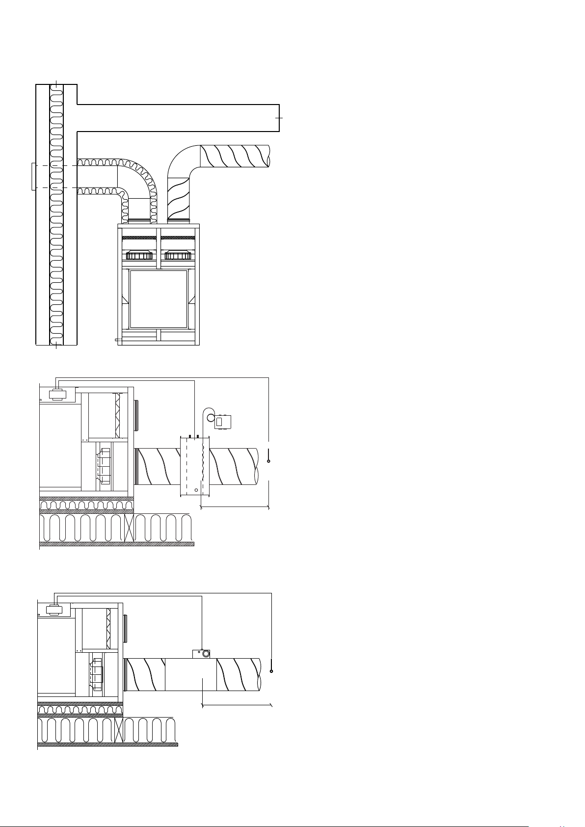
Reheating supply air
The counter flow heat exchanger cannot fully recover all
heat from exhaust air to supply air, so during winter the
supply air will be approximately 1-4°C lower than the
ambient temperature in the property. If the system is
intended for use in heating, then a water or electric heating
surface can be installed to heat the supply air to room
temperature.
Water heating surface
To protect the water heating surface against frost damage,
a water frost sensor must be installed on the system and
the water heating surface must be insulated. The water
frost sensor is installed on the back of the slats of the
water post-heating surface. The sensor for controlling the
motor valve is installed in the supply air duct approximately
500 mm after the water heating surface so that it is not
affected by radiant heat from the heater. The water con-
nection to the water heating surface must be carried out by
an authorised plumber.
Electric heating surface
The sensor for controlling the electric heating surface is
installed in the supply air duct approximately 500 mm after
the electric heating surface so that it is not affected by
radiant heat from the heating unit.
With water heating surface
With electric heating surface
10
Inhaltsverzeichnis
Andere Genvex Lüfter Handbücher

Genvex
Genvex ECO 360 R Bedienungsanleitung

Genvex
Genvex GE ENERGY 3 Bedienungsanleitung

Genvex
Genvex ECO 375 TS Bedienungsanleitung

Genvex
Genvex ECO 375 Bedienungsanleitung

Genvex
Genvex ECO 190 CS/CL Bedienungsanleitung

Genvex
Genvex ECO 190 XL Bedienungsanleitung

Genvex
Genvex ECO 275 Bedienungsanleitung

Genvex
Genvex ECO 300 Bedienungsanleitung

Genvex
Genvex OPTIMA 270 Bedienungsanleitung


