i-CAT FLX Bedienungsanleitung
Installation Manual
Cone Beam 3D +
2D Panoramic Dental
Imaging System
TM
TM

i-CAT FLX Installation Manual
032-0330-EN Rev K
IMPORTANT! . . . X-RAY PROTECTION
X-ray equipment may cause injury if used improperly. The instructions contained in this
manual must be read and followed when installing this scanner. The scanner provides a
high degree of protection from unnecessary X-radiation. However, no practical design can
provide complete protection, nor prevent operators from exposing themselves or others to
unnecessary radiation. It is important that you become fully acquainted with applicable
government radiation protection regulations. Many provisions of these regulations are
based on the recommendations of the National Council on Radiation Protection and
Measurements. Recommendations for dental X-ray protection are published in NCRP
Report Number 35 available from NCRP Publications, 7910 Woodmont Ave., Suite 800,
Bethesda, MD (USA) 20814, or at www.ncrp.com. Personal radiation monitoring and
protective devices are available. You are urged to use them to protect against unnecessary
X-radiation exposure.

-iii
032-0330-EN Rev K
Table of Contents
TABLE OF CONTENTS
Supplemental Components ............................................................................-vii
PAN Scan Components .................................................................................-viii
Chapter 1 - Scanner Assembly
Install Scanner .................................................................................................1-1
Install Retention Brackets ............................................................................1-11
Install Scanner Controller, Touch Screen and Keyboard ..........................1-13
Level Gantry ...................................................................................................1-14
Check Version of SmartScan STUDIO .........................................................1-16
Set Scanner Controller Date, Time, and Time Zone ...................................1-16
Change Settings of Support URLs (Optional) .............................................1-16
Chapter 2 - Calibration and Laser Adjustments
Panel Calibration .............................................................................................2-2
Run Panel Calibration .............................................................................................2-2
Adjust Crosshair Laser ...................................................................................2-2
Patient Chair Alignment ..................................................................................2-5
Install Chair Calibration Fixture .............................................................................2-5
Run Chair Calibration .............................................................................................2-6
Adjust Centerline Laser ..................................................................................2-7
Geometric Calibration .....................................................................................2-9
Install Geometric Calibration Fixture .....................................................................2-9
Run Geometric Calibration .....................................................................................2-9
Shutter Calibration ........................................................................................2-11
Run Shutter Calibration ........................................................................................2-12
Head Holder Alignment .................................................................................2-12
Chapter 3 - Load Clinical Software and Configure System
Software Installation Overview ......................................................................3-1
Site IT Network Setup ......................................................................................3-5
Network Access Permissions ................................................................................3-5
SmartScan STUDIO Manager Status Indicators ...................................................3-6
Fixed IP Addresses .................................................................................................3-8
Risk of Changes to Site Network ...........................................................................3-9
Alternate Network Configurations .......................................................................3-10
Scenario 1 - i-CAT FLX Installation ..............................................................3-11
Scenario 2 - Replace Existing i-CAT 17-19 or KaVo 3D eXam with an
i-CAT FLX (without DEXIS) ...........................................................................3-12
Scenario 3 - New DEXIS - i-CAT FLX Installation .......................................3-13

-iv
i-CAT FLX Installation Manual
032-0330-EN Rev K
Scenario 4 - Upgrade Existing DEXIS (without i-CAT 17-19
or KaVo 3D eXam) with DEXIS - i-CAT FLX .................................................3-15
Install and Configure Clinical Software .......................................................3-17
Install SmartScan STUDIO Server Components .................................................3-17
Install SmartScan STUDIO Client Components ..................................................3-21
Install TxSTUDIO Software ...................................................................................3-24
Configure SmartScan STUDIO PACS Modules (Optional) .................................3-26
Configure Legacy Practice Management Interface (Optional) ..........................3-30
Installation Check ..........................................................................................3-31
Installation Check for i-CAT FLX Installation ......................................................3-31
Installation Check for a DEXIS i-CAT FLX Installation .......................................3-32
Chapter 4 - QA Tests
Run QA Tests ...................................................................................................4-1
QA Line Pair Test .............................................................................................4-1
Set Up QA Phantom ................................................................................................4-1
Run QA Line Pair Test ............................................................................................4-2
QA Line Pair Evaluation ..........................................................................................4-3
Distance Measurement Test ...................................................................................4-4
QA Material Test ..............................................................................................4-4
Set Up QA Phantom ................................................................................................4-4
Run QA Material Test ..............................................................................................4-4
QA Material Evaluation ...........................................................................................4-5
QA Air Water Test ............................................................................................4-7
Set Up QA Air Water Phantom ...............................................................................4-7
Run QA Air Water Test ............................................................................................4-8
QA Air Water Test Evaluation .................................................................................4-8
QA PAN Test ..................................................................................................4-12
Install PAN Phantom .............................................................................................4-12
Run QA PAN Test ..................................................................................................4-12
QA PAN Test Evaluation .......................................................................................4-13
Safety Checks (Optional) ..............................................................................4-13
Chapter 5 - Complete Installation Forms
Appendix A - Wall Mounting Operator Control Box
Wall Mount with Cable Exposed ...................................................................A-1
Wall Mount with Cable Inside Wall ................................................................A-4
Appendix B - Service Menu Options
Scanner Startup ..............................................................................................B-1
Power Up ................................................................................................................. B-1
Log in ....................................................................................................................... B-1
Run Utilities ..................................................................................................... B-2

-v
032-0330-EN Rev K
Table of Contents
Scanner Shutdown ......................................................................................... B-2
Log out .................................................................................................................... B-2
Power Off ................................................................................................................ B-2
Appendix C - Setup of Alternative Network Configurations
Remote Image Root Setup for Domain Environment .................................. C-1
Remote Network Share Using Windows Workgroup Environment ...........C-6

-vi
i-CAT FLX Installation Manual
032-0330-EN Rev K
-vii
Supplemental Information
032-0330-EN Rev K
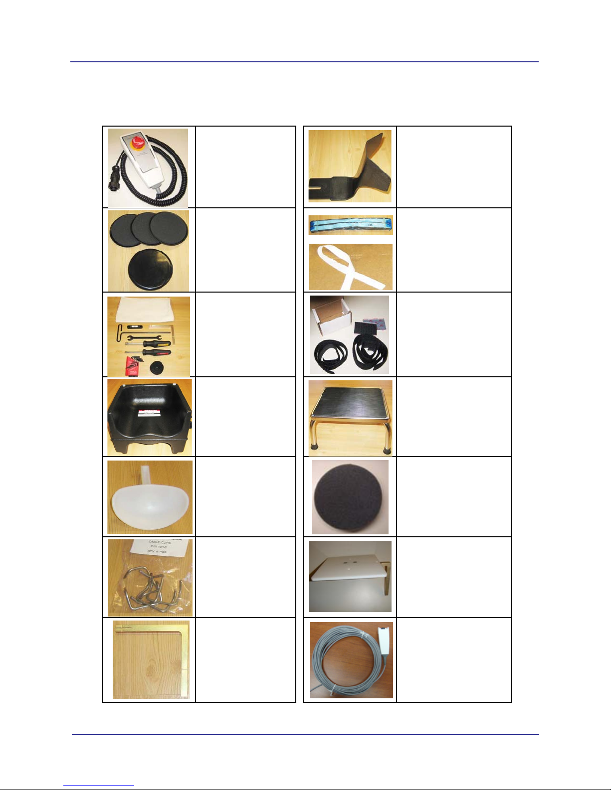
Supplemental Components
Patient E-stop
Part # 1304-0
Quantity 1
Carbon Fiber Head Rest
Part # 27-0
Quantity 1
Glide
Part # 910-24
Quantity 4
Head Restraint Band
Part # 27-1
Quantity 50
Tool Kit
Part # 910-22
Quantity 1
Velcro Head Restraint
Kit
Part # 903-0
Quantity 1
Booster Seat
Part # 1000196
Quantity 1
Available on request
Foot Stool
Part # 1000197
Quantity 1
Chin Cup
Part # 9140-0026-
0006
Quantity 1
Foam Disk
Part # 1000323
Quantity 1
Cable Clips
Part # 101-6
Quantity 6
Platform Assembly
Part # 14-4-0
Quantity 1
Chair Calibration
Fixture
Part # 26-16
Quantity 1
Handswitch (optional)
Part # 1.010.3959
Quantity 1
-viii
i-CAT FLX Installation Manual
032-0330-EN Rev K
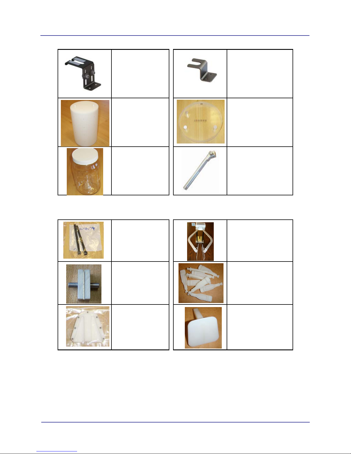
PAN Scan Components
Cord Retention
Bracket
Part # 1.012.6471
Quantity 1
Overhead Cord Bracket
Part # 1.012.5468
Quantity 1
GeoCal Fixture
Part # 14-1-0
Quantity 1
QA Phantom
Part # 13-00
Quantity 1
Water Jar Phantom
Part # 1000224
Quantity 1
Chin Rest Slide, Straight
Part # 36-1-0
Quantity 1
Bite Tip Holder
Part # 980220
Quantity 2
PAN Head Holder
Part # 33-0
Quantity 1
Position Alignment
Tool
Part # 33-19
Quantity 1
Bite Tip
Part # 26-15
Quantity 25
Pan Phantom
Part # 12-0
Quantity 1
Chin Rest
Part # 26-12
Quantity 1
1-1
032-0330-EN Rev K
Chapter
1 Scanner Assembly
NOTE: Do NOT begin installation of any equipment or software unless the Preinstall Checklist (ISI-MKTG-
CS-0007) has been completed for the site.
Install Scanner
There are two methods used for shipping the scanner, assembled and non-assembled. Start with one for
thenon-assembledscanner.Startwithstep13forscannersthatareshippedassembled.Beforemovingthe
scanner into place, ensure that the area is clean and that there is ample room to work.
WARNING
This scanner has assemblies that require a two person lift. Failure to comply may cause bodily
injury. Two adults are required to unpack and assemble this scanner.
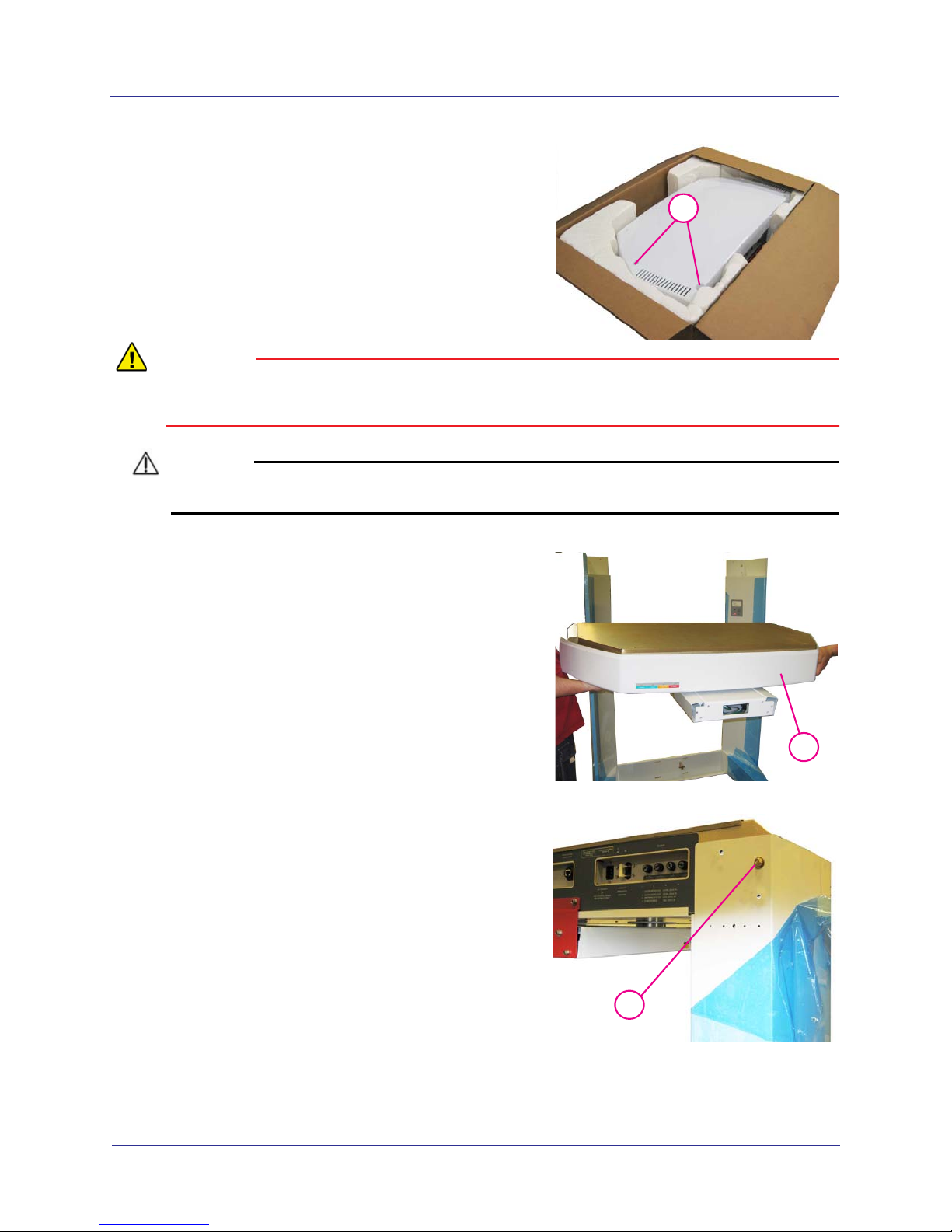
CAUTIONCAUTION
Follow instructions on all shipping labels to ensure proper handling of the scanner. For scanners
that are shipped assembled, the chair column must be removed from the scanner before moving
scanner into place. Remove four screws at rear of chair column to remove column. Moving
scanner with the chair column attached may cause damage to the equipment.
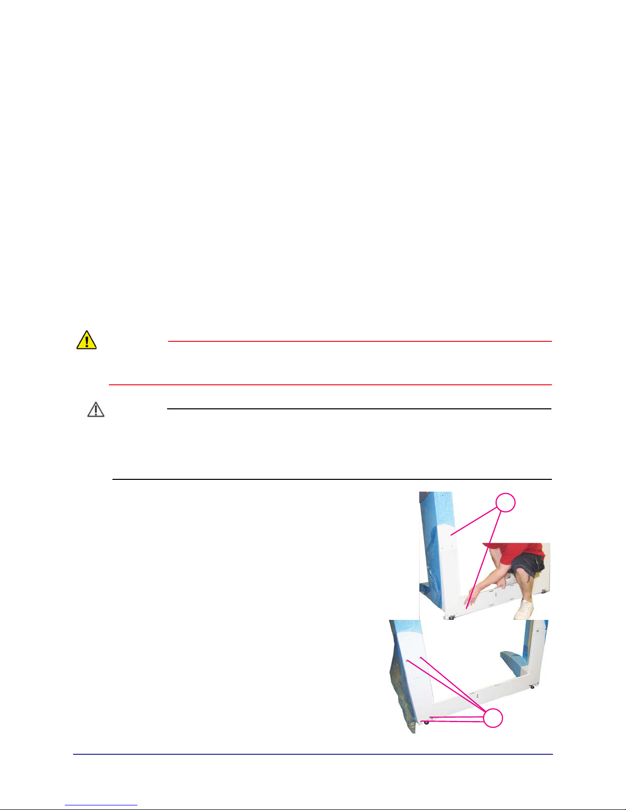
1. 1
With the help of an assistant, install the lower plate
under the two leg assemblies, as shown.
2.
23/16
Attach with mounting hardware, four SHCS 1/4-20 x 5
long with1/4” split washers, both sides.
1-2
i-CAT FLX Installation Manual
032-0330-EN Rev K
3.
33/32
Remove both top covers (six mounting screws).
WARNING
This scanner requires a two person lift. Failure to comply may cause bodily injury. Two adults are
required to assemble this scanner.
CAUTIONCAUTION
Use extreme care not to scratch overhead assembly when mounting scanner onto leg assemblies.
4.
4
With an assistant, lift overhead into place on top of
leg assemblies.
5.
5
Ensure the pins on rear of the overhead are seated
into the holes on leg assemblies.
Andere Handbücher für FLX
1
Inhaltsverzeichnis
Andere i-CAT Dentalgeräte Handbücher


Beliebte Dentalgeräte Handbücher anderer Marken

Vatech
Vatech EzRay Air VEX-P300 Bedienungsanleitung

KaVo
KaVo GENTLEpower LUX Contra-angle 25 LP Bedienungsanleitung

DENTSPLY
DENTSPLY SmartLite Focus Bedienungsanleitung

LM
LM ProPower CombiLED Bedienungsanleitung

Owandy Radiology
Owandy Radiology RX-AC Bedienungsanleitung

mectron
mectron Piezosurgery Bedienungsanleitung


