
I-Gard IPC DSP OHMNI Bedienungsanleitung

Instruction Manual C-409
HIGH RESISTANCE
GROUNDING SYSTEM
DSP OHMNI
DSP OHMNI
the power to protect

HIGH RESISTANCE GROUNDING
IMPORTANT
Each DSP module is carefully inspected before packed in a specially designed carton. The unit should be examined
immediately upon receipt. If damage or indication of rough handling is apparent, a claim should be filed without
delay with the transport company. I-Gard should be notified promptly if replacements for damaged goods are
necessary. If units received are not to be installed immediately they should be stored in their original containers in an
area free of dust and moisture.
DSP Second Fault Protection – unnecessary outages of electrical power in continuous process industries or
in critical systems applications such as hospitals, air traffic control towers etc cannot be tolerated and this has
increased the usage of high resistance grounding systems.
The new DSP Ohmni System is designed to provide an alarm, but not trip when one ground fault occurs in the
system thus retaining system continuity. If a second fault develops on the system, before an existing fault has
been cleared, then the potential for serious damage results.

TABLE OF CONTENTS
1 Introduction 3
2Application 4
3Installation 5
4Wiring 6
5Display 10
6Setup 11
7Operation 18
8Alarm Indications 20
9 Self-Test 22
10 Events 23
11 Maintenance and Testing 24
12 Service 25
13 Communications 25
14 Specifications 31
15 Outline Dimensions 33
16 Additional Information 36
17 Instruction Manuals ibc
TABLES
Table 3.1 System Module Requirements 5
Table 3.2 Standard Ribbon Cables 5
Table 6.1 Pulsing Frequency Selection 17
Table 13.1 MODBUS RTU Standard 8 Byte Holding Register Read Function (03) 26
Table 13.2 Returned Information Structure for Holding Register Request 26
Table 13.3 Request to Write to Set a Bit on a Register (Modbus Force Coil) 26
Table 13.4 Returned Information from Dsp Following a Force Bit Request 27
Table 13.5 Feeder Module Ground Current Addresses 28
Table 13.6 Feeder Module Status Addresses 29
Table 13.7 Feeder Module Priority Addresses 30
Table 13.8 System Function Registers 31

I-GARD DSP-OHMNI Instruction Manual
2
TABLE OF FIGURES
Figure 4.1 a) Typical One-Line Installation - Unit Substation b) System Module DSP-DSM Wiring 7
Figure 4.1 c) Power Supply DSP-DPS wiring 7
Figure 4.2 Preferred Feeder Module DSP-DFM Wiring 8
Figure 4.3 Alternative Sensor Wiring 8
Figure 4.4 Typical 4-wire Communications Connection 9
Figure 4.5 Alternative two-wire connection for RS-485 10
Figure 5.1 Home Screen 10
Figure 5.2 Alarm Screen 10
Figure 6.1 Communications Set-up 11
Figure 6.2 Communications Set-up 11
Figure 6.3 Grounding Resistor Set-up 12
Figure 6.4 Feeder Module Set-up 12
Figure 6.5 I/D Check indication 13
Figure 6.6 Feeder Module Set-up 14
Figure 6.7 a) Feeder Module Successful b) Set-up Not Successful 14
Figure 6.8 a) DSP-DM allows further Feeder Module set-up b) If previous set-up had not been successful 14
Figure 6.9 Pulse Set-up Request 15
Figure 6.10 Pulse Mode Set-up 15
Figure 6.11 Typical Examples of Pulse Circuit Connection 16
Figure 6.12 Alarm relay Setup 17
Figure 6.13 Alarm relay Options 17
Figure 6.14 Save Screen 18
Figure 6.15 Self-Test Prompt 18
Figure 7.1 Normal Home Screen 18
Figure 7.2 System leakage current lG19
Figure 7.3 Feeder Current IGf 19
Figure 7.4 Trip Defeated 19
Figure 7.5 Pulse Control 20
Figure 7.6 New Home screen indicates Pulsing ON 20
Figure 8.1 Alarm Screen 21
Figure 8.2 Bus Fault 22
Figure 9.1 System-Test Prompt 22
Figure 9.2 Prompt for Feeder Test 22
Figure 9.3 Feeder Module Test 23
Figure 9.4 Test Result 23
Figure 10.1 Event Notification 23
Figure 10.2 Momentary Feeder Fault Example 23
Figure 15.1 DIN Rail Mounted Modules 33
Figure 15.2 DSP-DM Display Module with cut-out detail 34
Figure 15.3 DSP-DPS Power Supply Connections 35
Figure 15.4 DSP-DSM System Module Connection 35
Figure 15.5 DSP-DFM Feeder Module Connection 35
Figure 15.6 DSP-DM Display Module Connections 36

DSP-OHMNI Instruction Manual I-GARD
3
1INTRODUCTION
High-Resistance-Grounding is becoming more prevalent in industrial and commercial electrical power
systems. As the need for reliable and stable power increases the inconvenience of unwanted downtime
in processing, robotics and data service also become more critical and costly.
Single Ground Faults in motors and equipment are common and will cause interruption of service
in Solidly Grounded systems. HRG prevents this event from happening by limiting the fault current to
a sustainable level for an indefinite time.
The DSP system is designed to detect the event of a single fault and signal an alarm condition and point
to the affected branch or feeder. Thus maintenance can be immediately alerted to the problem and an
operator dispatched to locate the fault to isolate it promptly. The DSP system can assist in locating the
fault with a pulsing fault location circuit that modulates the current in the fault. This allows the operator to
identify which branch circuit is carrying fault current using a portable clamp-on current probe connected
to an ordinary Multi-meter.
The DSP system consists of a number of modules that are mounted on a 35mm DIN rail typically located in
a control compartment of switchgear. The modules are connected together through 20-conductor
standard ribbon cable. A panel-mounted Display module provides a human interface to the system
and communications to a RS-485 network allows set-up and control.
There are four DSP modules as follows:
DSP-DM Display Module
DSP-DPS Power Supply
DSP-DSM System Module
DSP-DFM Feeder Module
The Display Module is a panel-mounted enclosure designed for flush mounting in a door. It is connected by
a ribbon cable to the Power Supply unit. The DSP-DM indicates faulted phase, total
system leakage current, feeder branch current level and provides other information such as priority
settings and Resistor setting etc. It is used to set-up the system and provide manual control of the
pulse location system.
The POWER Supply unit DSP-DPS is a DIN rail-mounted modular unit constructed with an ABS enclosure
and provides +5V, +12V and -12V regulated supplies to all of the modules through the front ribbon cables. It
is capable of operation with a wide range of voltage supplies from 100V to 240V ac without selection of any
jumpers or switches. DC voltage can also be used from 125V to 250V DC.
The System Module monitors the system line-to-ground voltages through a standard I-Gard Corp. DDR2
voltage dividing resistor unit. It determines if there is voltage unbalance in the system and the level
of ground fault current in the grounding resistor, without any connection to the Resistor.

I-GARD DSP-OHMNI Instruction Manual
4
The Feeder Modules measure the fault current level in the branch circuits that are protected. This module
uses standard I-Gard current sensors Type T2A, T3A, T6A and T9A. It is equipped with a form C 10A
output Relay that can be used for breaker control. The DSP-DFM detects two fault levels. Firstly it detects
the single fault, which creates a System Alarm condition, and secondly through a priority level system it
provides breaker control to disconnect the least important circuit breaker.
Communications is provided by a 4-wire RS-485 network connection from a jack located at the rear of the
DSP-DM Display module. The communications protocol supported is MODBUS RTU, which is a master/
slave system with selectable baud rates from 4800 to 19200. The DSP supports the MODBUS function Read
Holding Registers only, without exception support. Additionally it will support remote RESET using the Force
Coil function.
2APPLICATION
The DSP system is used in conjunction with I-Gard, Alarm Resistor Unit Type DDR2. The DDR2 matches
the DSP-DSM input circuits to the system voltage and is available in 4 types as follows:
Type System Voltage
DDR2-1 120V*
DDR2-2 240V
DDR2-4 480V
DDR2-6 600V
* Also used with potential transformers up to 13.8KV
The DDR2 provides output voltages VAG, VBG, VCG that are proportional to the phase to ground voltage and
also voltage VNG that is proportional to the neutral resistor voltage. ( i.e. Total leakage/fault current of the
system)
On large systems provision is usually made to ground the system using a current-limiting resistance
(I-Gard Type OHMNI-PM or NGR). On ungrounded systems there is always leakage capacitance to ground
from each line. Re-striking ground faults may cause an excessive build up of line to ground voltage due to
this capacitance. It may be stabilized with the addition of a grounding resistance, thus preventing costly
breakdown of insulation.
The Type OHMNI-PM is connected between ground and the star point of the transformer on Wye systems.
On Delta systems an artificial neutral device (I-Gard Type DDAI) is required to provide a star point. Both
OHMNI-PM and DDAI devices are selected for appropriate current ‘let-through’,i.e.: The current, which will
flow to ground, if there is a direct short from line to ground (on any one phase).
NOTE: A good Rule-of-Thumb for Resistor current selection is 1 ampere per 2000KVA, if no surge capacitors are on the system,
and 1 ampere per 1000KVA with surge capacitors. For further information please refer to www.i-gard.com/appguides.htm

DSP-OHMNI Instruction Manual I-GARD
5
DDAI and OHMNI-PM devices are available for continuous currents of 1 ampere to 10 amperes for
most systems. For further information regarding the use of these devices refer to:
Instruction Manual Type DDAI Artificial Neutrals C-430EM
Instruction Manual Type DDR2 Alarm Resistor Units C-440EM
Instruction Manual Type OHMNI-PM Neutral Grounding Resistors C-450EM
3INSTALLATION
A typical installation will include for each power source (transformer/generator) 1 DSP-DM, 1 DSP-DPS,
1 DSP-DSM and a number of DSP-DFM Feeder Modules as required with 1 for each branch protected.
Additionally there will be a DSP-PM pulsing resistor to ground the system. A voltage-sensing resistor DDR2
is required for the DSP-DSM input, as well as one current sensor for each DSP-DFM for current detection.
See Table 3.1 for typical requirements.
TABLE 3.1 SYSTEM MODULE REQUIREMENTS
Catalog Number Description No Required/System
DSP-DM Display Module 1
DSP-DPS Power Supply 1
DSP-DSM System Voltage Module 1
DSP-DFM Feeder Module As required 1/ Circuit
OHMNI-PM Pulse Equipped Resistor 1
DDR2 Voltage Sensing Resistor 1
DDAI Artificial Neutral Required only for delta system
T Toroidal Current Sensor 1/Feeder Module
TABLE 3.2. STANDARD RIBBON CABLES
Length Function Catalog Number
365cm (12ft) DSP-DM to DSP-DPS DRC-365
150cm (5ft) DSP-DM to DSP-DPS DRC-150
5cm (2 in.) Module to Module connection RC-3
30cm (12 in.) Module to Module connection RC-30
DSP modules are mounted on a 35mm DIN Rail generally located at the rear wall of a switchgear
compartment. They should be mounted side by side and connected with 20-conductor ribbon cable in a
daisy chain configuration. This applies to the DSP-DPS, DSP-DSM and DSP-DFM modules only.

I-GARD DSP-OHMNI Instruction Manual
6
DSP (Outline Dimensions). Care should be taken not to over tighten the 8-32 nuts used to retain the
DSP-DM
It will be necessary to provide a reliable power source (which is not interrupted by operation of the DSP
output contacts) for control power. The supply should be 100-240 V AC/DC. The control supply must be
fused by 1 Ampere fuses as shown in Fig. 4.1 a (Connection Diagram). Ideally the alarm, warning bell should
be connected to a separate control supply from the DSP (see para. 8.3.1).
4WIRING
No.14 or No.16 switchboard wire is used for all current sensor, control and DDR2 connections, which need
not be shielded. 4-wire shielded cable should be used for the serial communications, however. A typical
wiring schematic is shown in Figure 4.1a.
Sensor wiring is not generally limited by length and may be up to a kilometer without degradation of
performance, since the sensor is a current source. Sensor wiring should be run in separate conduit from
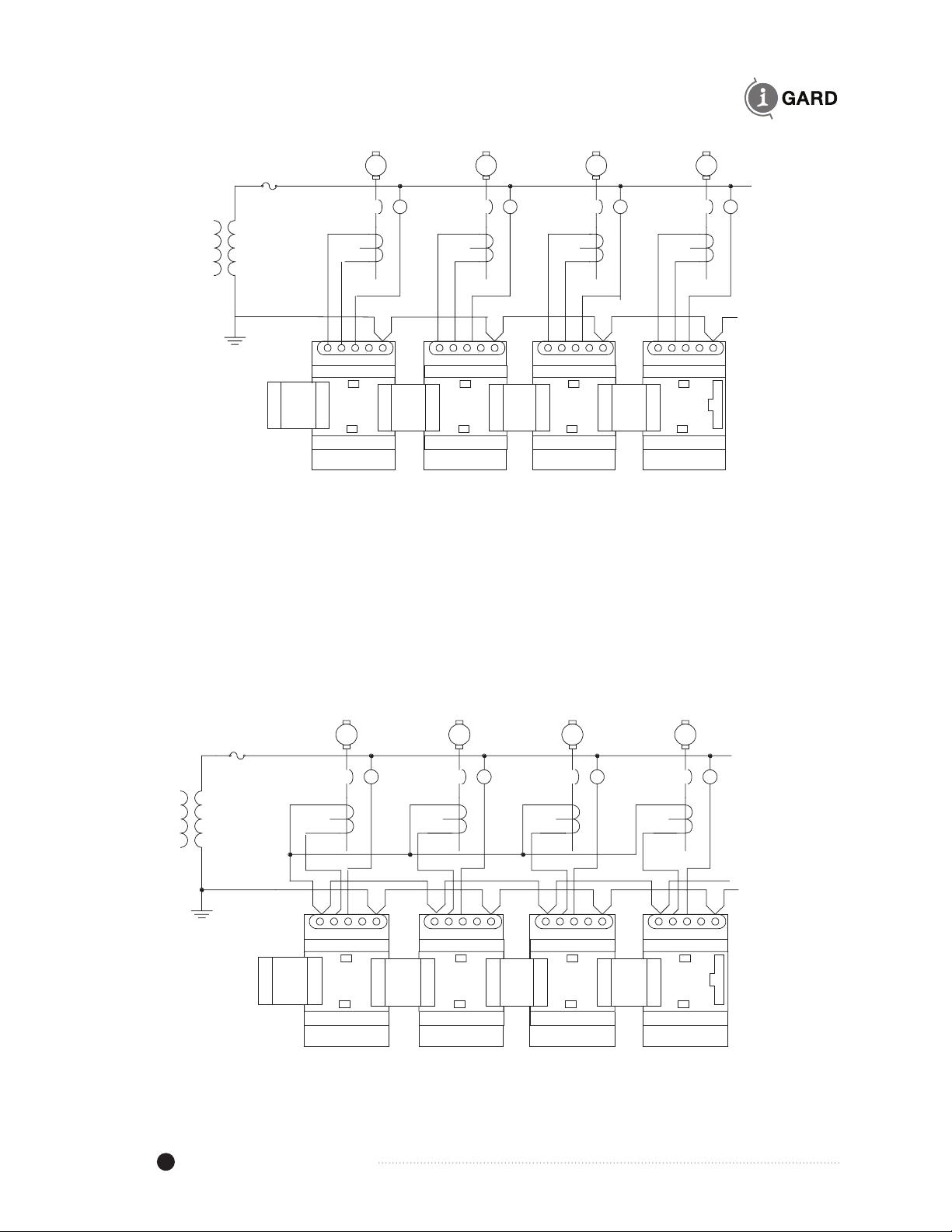
Power wiring. The recommended sensor wiring connections are shown in Figure 4.2. Two wires should
be run from each sensor X1 and X2 as indicated to prevent cross coupling between Modules. If existing
wiring does not allow this connection because of common connection at X2 as has been common in some
installations, then the G terminals of the DSP-DFM modules should be connected as shown in Figure 4.3.
Ribbon cables are available in different lengths as shown in Table 3.2. For other lengths contact
I-Gard. The DRC-cable from the DSP-DM to the DSP-DPS, apart from being different in length, also differs
in the orientation of the connector. This allows the cable to be run easily from the DSP-DM towards the
DSP-DPS power supply. The RC-cables are used for Module to Module connections and are short in
length. Note the orientation of the plug as marked on the DSP-DM display module. If a second row of
modules is installed on another DIN rail,the last module on the right can be connected to the last module
on the right on the second row using the RC-30 cable. Either slot can be used on the DSP-DFM feeder
modules for connection.

DSP-OHMNI Instruction Manual I-GARD
7
13 15 17
GCA
TO DDR2-
RESISTOR
BN
14 16
Figure 4.1b System Module DSP-DSM Wiring
27 29 31 33 34 36 38 40 41
NC COM NO + - VAC VAC G G
100-240V
ALARM
RELAY TO
HORN
12V DC
PULSE
OUT
SYSTEM
GROUND
CONTROL
1A1A
Figure 4.1c Power Supply DSP-DPS wiring
DDR2
25VA CPT
120V
OHMNI-PM NGR
MAIN BUS
HORN
1A
PULSE SIGNAL
DSP-DSM
ZSCS
BREAKER
TRIP SIGNAL
ALARM
CONTACTS
ABCNG
AB NGC
POWER
AC/DC
DSP-
DFM
LOADS
DSP-
DFM
DSP-DPS
DSP-DM
RS-485 TO NETWORK
DSP-
DFM
DSP-
DFM
1A
1A
N
G
20 COND
RIBBON
Figure 4.1a Typical One-Line Installation - Unit Substation
I-GARD DSP-OHMNI Instruction Manual
8
Figure 4.3 Alternative Sensor Wiring
Shunt Trip
Supply
Sensor 1 Sensor 2 Sensor 3 Sensor 4
To
DSP-DSM
G S NO NC COM
678910
DSP-DFM
G S NO NC COM
678910
DSP-DFM
G S NO NC COM
678910
DSP-DFM
G S NO NC COM
678910
DSP-DFM
Figure 4.2 Preferred Feeder Module DSP-DFM Wiring
NOTE: For Main-Tie-Main systems and multiple sources with tie breakers the priority buses can be joined together with the use
of I-Gard devices DSP-CAS and DSP-CA Modules. The DSP-CA module converts ribbon cable to an8-conductor shielded cable
for this purpose. The DSP-CAS does the same thing except that it includes an electronic switch to make or break the connections
when the tie breakers are closed or open. This eliminates the use of 8-pole contactor arrangements of previous systems. The two
modules are DIN rail mounted similar to the other DSP modules in 70mm wide housing. See information on DSP-CA(S) or manual
C-414EM for typical wiring.
Shunt Trip
Supply
Sensor 1 Sensor 2 Sensor 3 Sensor 4
To
DSP-DSM
X1
X2
X1
X2
X1
X2
X1
X2
G S NO NC COM
678910
DSP-DFM
G S NO NC COM
678910
DSP-DFM
G S NO NC COM
678910
DSP-DFM
G S NO NC COM
678910
DSP-DFM
Inhaltsverzeichnis
Andere I-Gard Schutzvorrichtung Handbücher


Beliebte Schutzvorrichtung Handbücher anderer Marken


nxt
nxt BIA-nXt-DPC 1-22 Bedienungsanleitung

TFortis
TFortis SG-Switch Bedienungsanleitung

BERNINI DESIGN
BERNINI DESIGN Be172 Bedienungsanleitung

Rayleigh Instruments
Rayleigh Instruments RI-ENERGYSET-3P-ESS-50-100 Bedienungsanleitung

GE
GE Multilin 3 Series Bedienungsanleitung

E.K.T.
E.K.T. ke-DP01 Bedienungsanleitung


