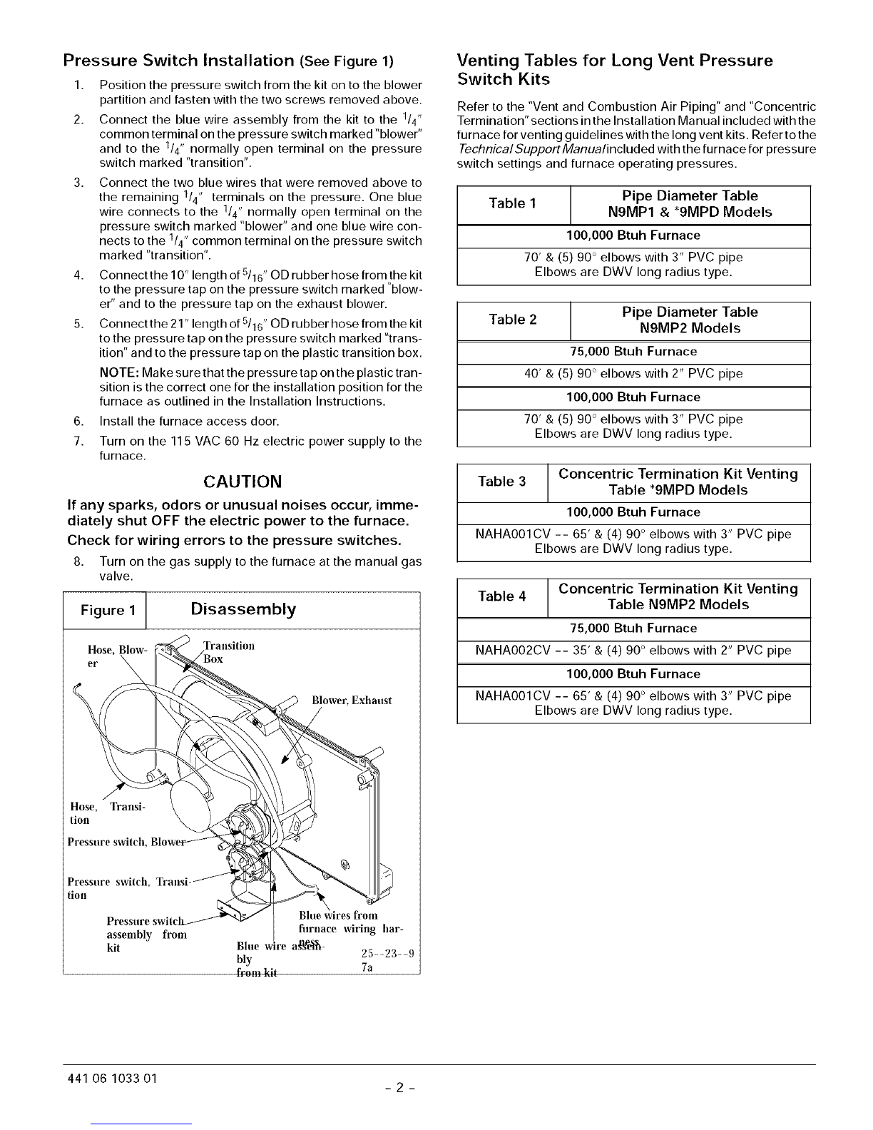
Pressure Switch Installation (See Figure 1)
1. Position the pressure switch from the kit on to the blower
partition and fasten with the two screws removed above.
2. Connect the blue wire assembly from the kit to the 1/4"
common terminal on the pressure switch marked "blower"
and to the 1/4" normally open terminal on the pressure
switch marked "transition".
3. Connect the two blue wires that were removed above to
the remaining 1/4" terminals on the pressure. One blue
wire connects to the 1/4" normally open terminal on the
pressure switch marked "blower" and one blue wire con-
nects to the 1/4" common terminal on the pressure switch
marked "transition".
4. Connectthe10"lengthofS/16"ODrubberhosefromthekit
to the pressure tap on the pressure switch marked "blow-
er" and to the pressure tap on the exhaust blower.
5. Connectthe21"lengthofS/16"ODrubberhosefromthekit
to the pressure tap on the pressure switch marked "trans-
ition" and to the pressure tap on the plastic transition box.
NOTE: Make sure that the pressure tap on the plastic tran-
sition is the correct one for the installation position for the
furnace as outlined in the Installation Instructions.
6. Install the furnace access door.
7. Turn on the 115 VAC 60 Hz electric power supply to the
furnace.
CAUTION
If any sparks, odors or unusual noises occur, imme-
diately shut OFF the electric power to the furnace.
Check for wiring errors to the pressure switches.
8. Turn on the gas supply to the furnace at the manual gas
valve.
Figure 1 ] Disassembly
Hose, Transition
er
Blower, Exhaust
Hose, Transi-
tion
Pressure switch,
Pressure switch,
tion
assembly from
kit Blue
bly
from ldt
froln
filrnace wiring har-
a_Fe_- 25::23::9
7a
Venting Tables for Long Vent Pressure
Switch Kits
Refer to the "Vent and Combustion Air Piping" and "Concentric
Termination" sections in the Installation Manual included with the
furnace for venting guidelines with the long vent kits. Refer to the
Technical Support Manualincluded with the furnace for pressure
switch settings and furnace operating pressures.
Table 1 Pipe Diameter Table
N9MP1 & *91VlPD Models
100,000 Btuh Furnace
70' & (5) 90 ° elbows with 3" PVC pipe
Elbows are DWV long radius type.
Table 2 Pipe Diameter Table
N9MP2 Models
75,000 Btuh Furnace
40' & (5) 90 ° elbows with 2" PVC pipe
100,000 Btuh Furnace
70' & (5) 90 ° elbows with 3" PVC pipe
Elbows are DWV long radius type.
Concentric Termination Kit Venting
Table 3 Table *9MPD Models
100,000 Btuh Furnace
NAHA001CV -- 65' &(4) 90° elbows with 3" PVC pipe
Elbows are DWV long radius type.
Concentric Termination Kit Venting
Table 4 Table N9MP2 Models
75,000 Btuh Furnace
NAHA002CV -- 35' & (4) 90° elbows with 2" PVC pipe
100,000 Btuh Furnace
NAHA001CV -- 65' & (4) 90° elbows with 3" PVC pipe
Elbows are DWV long radius type.
441 06 1033 01 2